Floating wind power platform with tension leg device

a technology of wind power platform and tension leg, which is applied in the direction of machines/engines, vessel construction, energy supply, etc., can solve the problems of high cost of manufacturing and transportation, increased space consumption of floating units, and increased space consumption of catenary mooring systems. , to achieve the effect of less material, less space consumption, and less material

Active Publication Date: 2020-11-12
FREIA OFFSHORE AB
View PDF0 Cites 0 Cited by
  • Summary
  • Abstract
  • Description
  • Claims
  • Application Information

AI Technical Summary

Benefits of technology

[0004]An object of the present invention is to alleviate some of the disadvantages of the prior art and to provide a floating wind power platform with weather vaning capabilities which requires less material during manufacturing, is cheaper to manufacture and is less space consuming and more compact yet provide sufficient stability. A further object of the present invention is to provide a floating wind power platform with an increased efficiency.

Problems solved by technology

Thus, the catenary mooring systems further require a significant use of the seabed space as well as material.
A drawback with known solutions is that the floating units are material—as well as space consuming, whereby both manufacturing and transport is expensive.
As a result, the manufacturing cost further increases.

Method used


Image

  • Floating wind power platform with tension leg device
  • Floating wind power platform with tension leg device
  • Floating wind power platform with tension leg device

Examples


Embodiment Construction

[0062]In the following, a detailed description of the invention will be given. In the drawing figures, like reference numerals designate identical or corresponding elements throughout the several figures. It will be appreciated that these figures are for illustration only and are not in any way restricting the scope of the invention. Swedish patent application 1850064-5 by the applicant is hereby incorporated by reference in its entirety. Protection may be sought for features in the referenced document Swedish patent application 1850064-5.

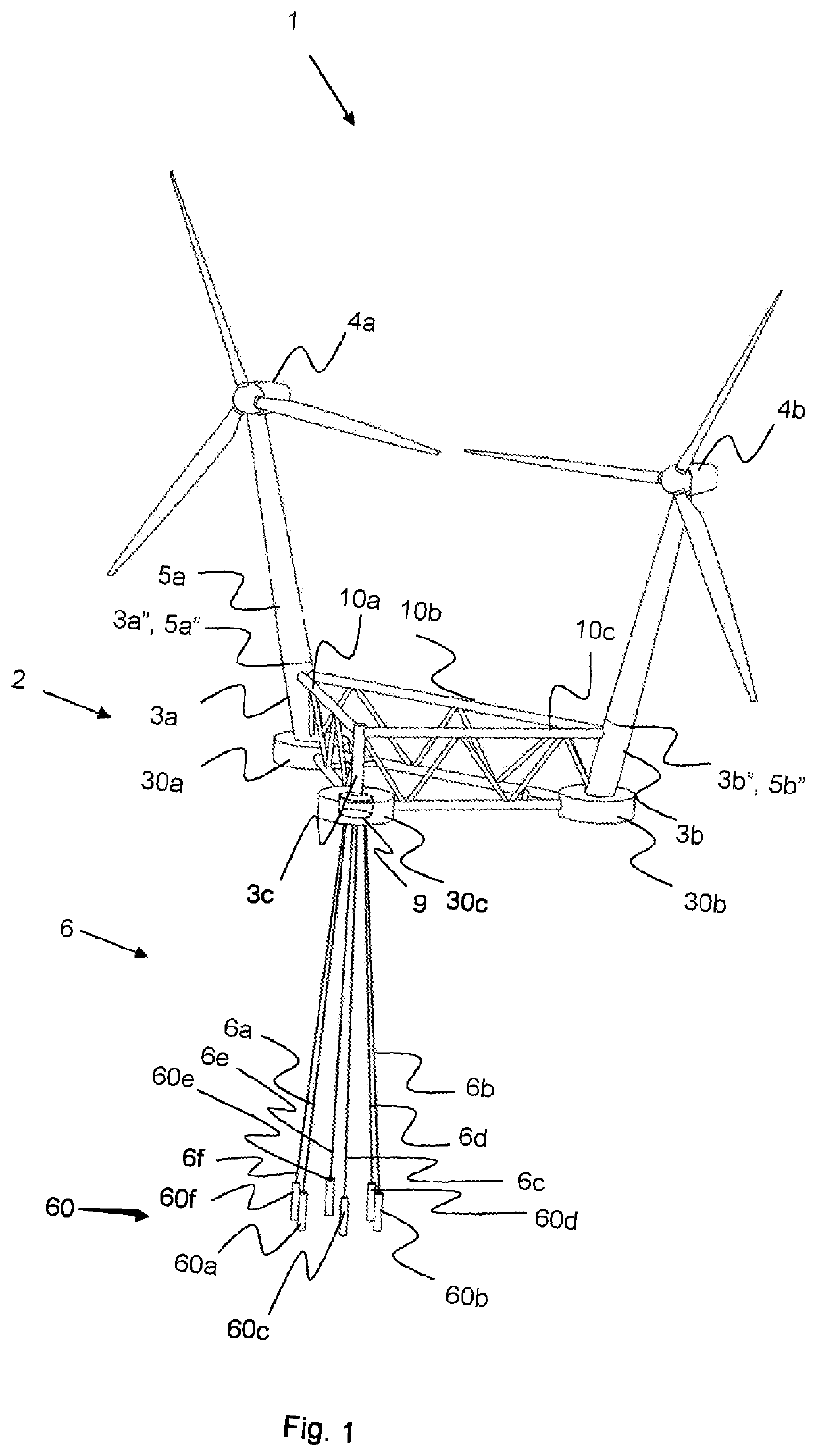
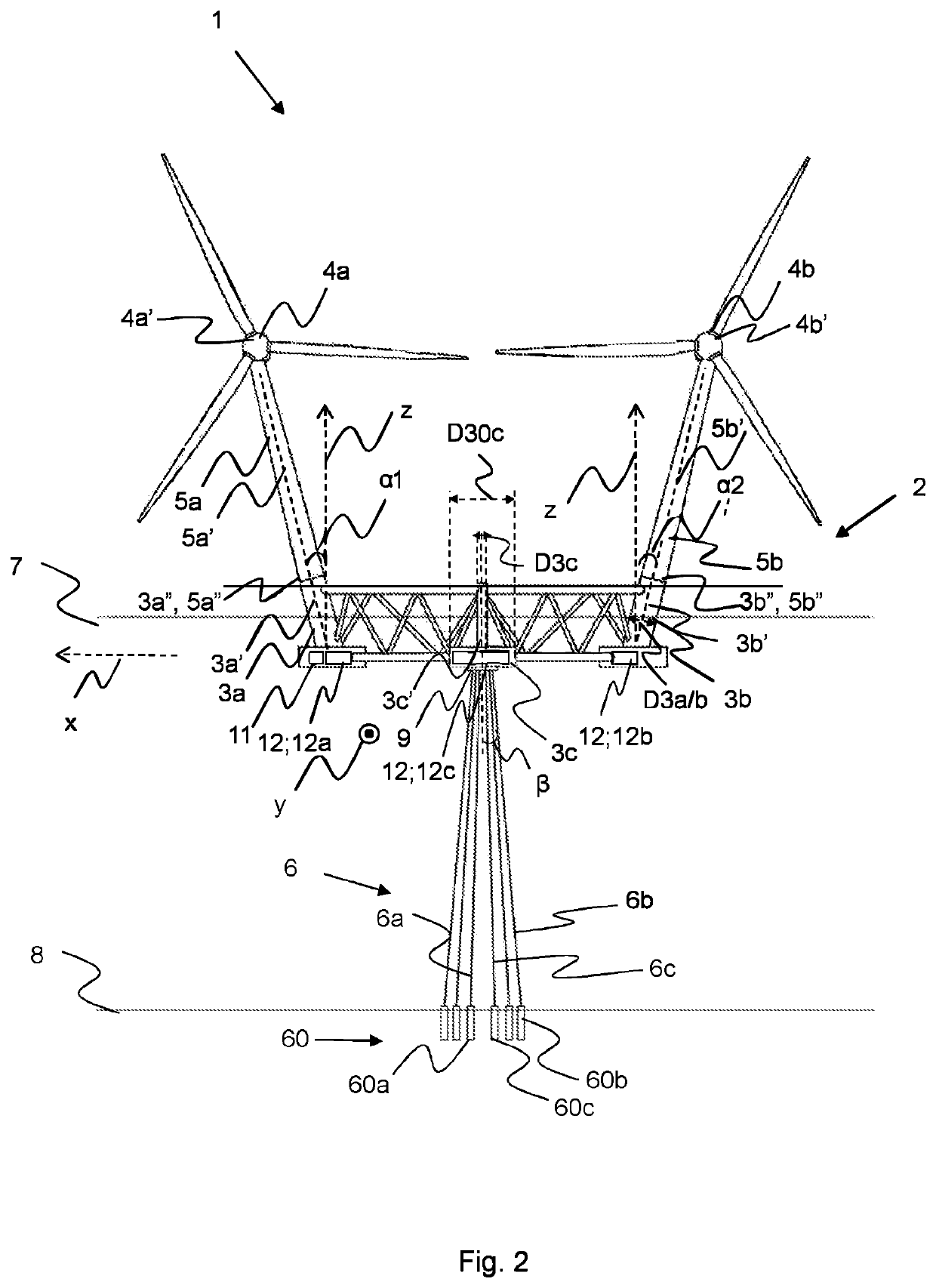
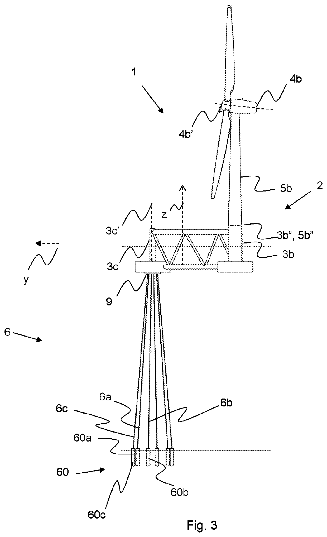
[0063]FIG. 1 shows a perspective view of a floating wind power platform 1 for offshore power production comprising a floating unit 2. According to one embodiment, the floating unit 2 comprises three interconnected semisubmersible columns 3a, 3b, 3c, i.e. a first, a second, and a third semisubmersible column 3a, 3b, 3c, each having a longitudinal column central axis 3a′, 3b′, 3c′ as can be further seen in FIG. 2. According to one embodiment, the flo...


PUM


Abstract

A floating wind power platform for offshore power production, comprising: a floating unit, wherein the floating unit comprises a first, a second and a third interconnected semisubmersible column each being arranged in a respective corner of the floating unit, wherein a tension leg device is arranged to the third semisubmersible column, wherein the tension leg device is adapted to be anchored to the seabed by an anchoring device, and wherein the third semisubmersible column provides a buoyancy force adapted to create a tension force in the tension leg device, wherein the floating wind power platform is further adapted to weather vane in relation to the wind direction.

Description

TECHNICAL FIELD[0001]The present invention relates generally to floating wind power platform.BACKGROUND ART[0002]It is known to use a catenary mooring system as anchoring system for floating wind power platforms for offshore power production. A catenary mooring system comprises a plurality of mooring points in the sea bed via catenaries. In order to increase stability of such floating wind power platforms in the horizontal plane, essentially to keep the platform upright in windy conditions and to prevent them from falling over, size, shape as well as weight distribution are critical parameters that need to be well balanced. For instance, larger platforms comprising a plurality of towers and turbines may often be adapted for weather vaning, and need to have a sufficient distance from the rotation point to the towers, but may also require a sufficient weight at the point of rotation to be sufficiently stable. Achieving stability for larger weather vaning systems are thus critical. Moo...

Claims


Application Information

Patent Timeline
Patent Type & Authority Applications(United States)
IPC IPC(8): F03D13/25B63B35/44
CPCF03D13/25F05B2240/93B63B2035/446B63B35/44B63B21/507B63B1/107B63B21/502B63B2001/128Y02E10/727Y02E10/72F05B2240/95F03D7/0204B63B2209/20F03D13/256F03D7/0202F05B2240/96B63B2241/08
Inventor HUMMEL, NIKLASRAHM, MAGNUSDYACHYK, EDUARD
Owner FREIA OFFSHORE AB
Why Eureka
Try Eureka