Electronic sphygmomanometer and a method for blood pressure measurement by using an electronic sphygmomanometer

Inactive Publication Date: 2012-05-31
OMRON HEALTHCARE CO LTD
View PDF11 Cites 1 Cited by
  • Summary
  • Abstract
  • Description
  • Claims
  • Application Information

AI Technical Summary

Benefits of technology

[0013]According to one or more embodiments of the invention, an electronic sphygmomanometer comprises: a cuff containing an air bladder for wrapping around a measurement area of a person being examined; an air charger for inflating the air bladder, an air discharger for deflating the air bladder, a sensor for detecting changes of pressure within the air bladder during the inflation and/or deflation of the air bladder;
[0014]According to one or more embodiments of the invention, an electronic sphygmomanometer comprises: a cuff containing an air bladder for wrapping around a measurement area of a person being examined; a pump for charging air to inflate the air bladder, a valve for releasing air to deflate the air bladder, a sensor for detecting changes of pressure within the air bladder during charging and discharging air to and from the air bladder; a memory for storing control programs, a reference blood pressure value, and a result of measurement of blood pressure; a display unit for displaying measured blood pressure, CPU for executing programs stored in the memory and calculating blood pressure of the person being examined based on the changes of pressure within the air bladder, the CPU further comprising: an estimation processing part for calculating an estimated blood pressure value of the person being examined based on the pressure change within the air bladder during the inflation of the air bladder at a first rate; and a measurement processing part for measuring a blood pressure value of the person being examined based on the pressure change within the air bladder during the deflation of the air bladder at a second rate; and a determination processing part for comparing the estimated blood pressure value obtained by the estimation processing with the reference blood pressure value and determining whether the estimated blood pressure value is within a predetermined range from the referenced blood pressure value. If the estimated blood pressure value is determined to be within a predetermined range from the reference blood pressure value, the display unit displays the estimated blood pressure value and measurement operation of the sphygmomanometer is ended.
[0015]According to one or more embodiments of the invention, an electronic sphygmomanometer comprises a cuff containing an air bladder for wrapping around a measurement area of a person being examined; means for inflating the air bladder, means for deflating the air bladder, means for detecting changes of pressure within the air bladder during the inflating and/or deflating the air bla

Problems solved by technology

In other words, securing highly precise measurements with either method requires slowing the speed of change in cuff pressure, and therefore the measurement time is longer.
However, the measurement time with this method requires roughly at least 40 seconds, and the need to increase the pressure by a prescribed amount higher than the systolic pressure is not resolved.
Therefore, measurement accuracy of the blood pressure value and the pulse rate measured during inflation has not been sufficient to enable use in blood pressure monitoring.
As the measurement time becomes longer, the measuring person may begin to feel annoyed at daily blood pressure measuring, which can become a primary factor in killing the desire to continue to measure especially for measuring blood pressure in the home.

Method used


Image

  • Electronic sphygmomanometer and a method for blood pressure measurement by using an electronic sphygmomanometer
  • Electronic sphygmomanometer and a method for blood pressure measurement by using an electronic sphygmomanometer
  • Electronic sphygmomanometer and a method for blood pressure measurement by using an electronic sphygmomanometer

Examples


first embodiment

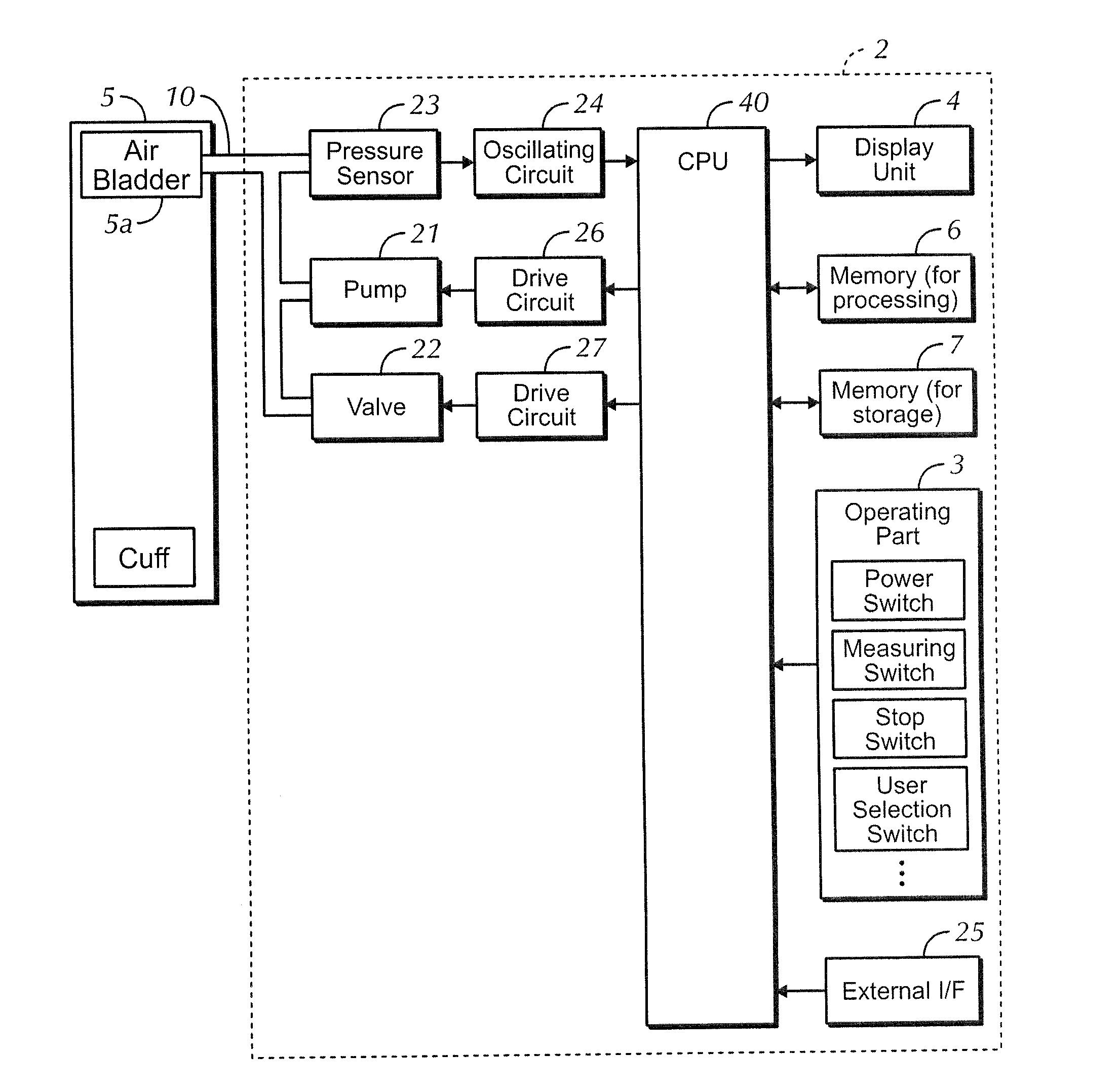
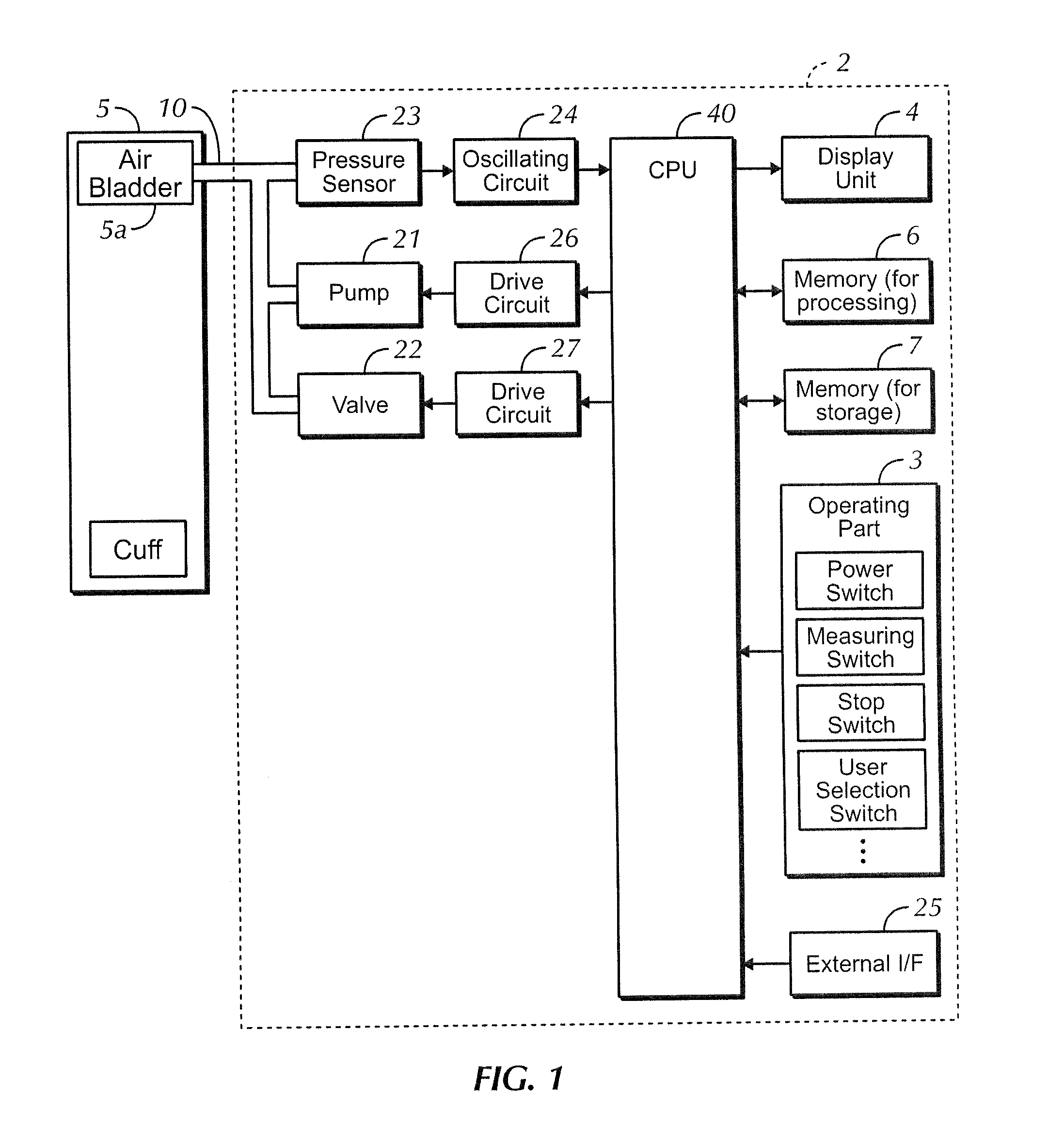
[0034]FIG. 1 is a block diagram illustrating a detailed example of one configuration of an electronic sphygmomanometer (herein after abbreviated as sphygmomanometer) that relates to the first embodiment of the present invention.

[0035]In referencing FIG. 1, the sphygmomanometer includes a cuff 5 which is a measuring band for wrapping around a measurement area such as the upper arm, a main body part 2, and an air tube 10 is connected to these. A display unit 4 and an operating part 3 are arranged on the face of the main body part 2.

[0036]The operating part 3 includes a plurality of switches such as a power switch for instructing the power to turn On / Off, a measuring switch for instructing the measurement operation to begin, a stop switch for instructing the measurement to stop, a user selection switch for selecting the person to be measured, and the like.

[0037]An air bladder 5A connected to an air tube 10 is included with the cuff 5. The main body part 2 of the sphygmomanometer 1 incl...

second embodiment

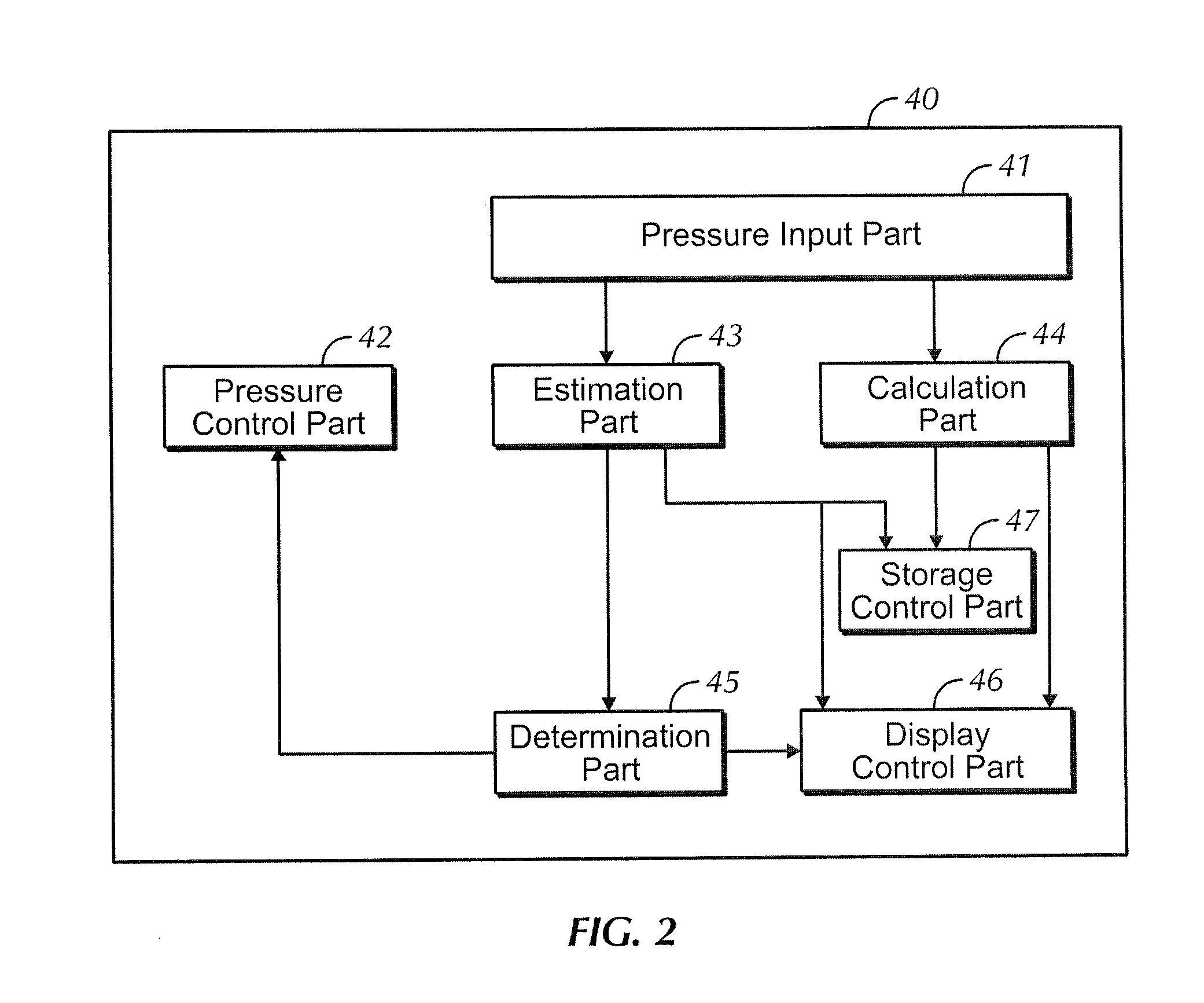
[0078]FIG. 9 is a block diagram illustrating a detailed example of a functional configuration of a sphygmomanometer 1 that relates to the second embodiment. In referencing FIG. 9, the CPU 40 in the second embodiment, in addition to the functions illustrated in FIG. 2, further includes an instruction input part 48 for receiving input of an operating signal according to an instructed operation by the user.

[0079]The display control part 46 performs a process to display on the display unit 4 operation buttons or a guide to the operation buttons according to the determination results by the determination part 45. Further, the instruction input part 48 receives input of an operating signal of an operation button according to a guide displayed on the display unit 4, or an instructed operation of an operation button displayed on the display unit 4. The internal pressure control part 42 performs pressure control within the air bladder 5A based on the operating signal received by the instruct...

third embodiment

[0099]FIG. 16 is a flowchart indicating an example of an operation in the third embodiment from among measurement operations in the sphygmomanometer 1.

[0100]In the operating example in the third embodiment with reference to FIG. 16, the user can select in the check step C (STC) whether to perform a simple check of the blood pressure. When the user selects to perform a simple check, it proceeds to the following simple check routine steps. If the user selects not to perform a simple check, the standard blood pressure measurement (measuring blood pressure by a deflation process of a cuff after inflating the cuff) is performed thereafter from step 10 and after.

[0101]When a simple check is selected to be performed at STC, the user inputs their ID (ST 3) if they have completed registration with the corresponding sphygmomanometer. When the user's ID is entered, the measured value for the history of the corresponding user stored in the memory 7 for storage is read. If the user has not yet r...


PUM


Abstract

An electronic sphygmomanometer includes a cuff containing an air bladder, an air charger, an air discharger, a pressure sensor, a memory; a display, and CPU for executing programs stored in the memory and calculating a blood pressure value based on the pressure changes within the air bladder. The CPU further includes an estimation processing part for calculating an estimated blood pressure value based on the pressure change within the air bladder during the inflation of the air bladder at a first rate, a measurement processing part for measuring a blood pressure value based on the pressure change within the air bladder during the deflation of the air bladder at a second rate, and a determination processing part for comparing the estimated blood pressure value with the reference blood pressure value and determining whether the estimated blood pressure value is within a predetermined range from the reference blood pressure value.

Description

BACKGROUND OF INVENTION[0001]The present invention relates to an electronic sphygmomanometer having a quick blood pressure checking function and a method of monitoring blood pressure using the electronic sphygmomanometer, and particularly relates to an electronic sphygmomanometer that monitors by measuring blood pressure using a cuff containing an air bladder and a method of monitoring blood pressure measurements with the electronic sphygmomanometer.[0002]Blood pressure is one indicator for analyzing circulatory diseases, and performing risk analysis based on blood pressure is effective at preventing diseases of the cardiovascular system such as strokes, heart failure, heart attacks, and the like.[0003]These diseases have conventionally been diagnosed by blood pressure (casual blood pressure) measured by a medical care provider during a patient visit or during a health checkup. However, through recent research, it is becoming clear that blood pressure measured at home (home blood pr...

Claims


Application Information

Patent Timeline
IPC IPC(8): A61B5/0225
CPCA61B5/0225A61B5/02141
Inventor SAWANOI, YUKIYAOGURA, TOSHIHIKO
Owner OMRON HEALTHCARE CO LTD
Why Eureka
Try Eureka