
Method, article of manufacture, and system for configuring controller in sliding-mode control scheme

Inactive Publication Date: 2012-05-31
IBM CORP
View PDF18 Cites 11 Cited by
  • Summary
  • Abstract
  • Description
  • Claims
  • Application Information

AI Technical Summary

Benefits of technology

[0025]A further advantage of the present invention is it becomes possible to avoid chattering and perform stable control for an accidental disturbance with an inexpensive controller. The advantage holds even for a system such as a satellite, in which it is difficult to install a high-speed switching function, etc. . . . .
[0026]Other characteristics and advantages of the invention will become obvious in combination with the description of accompanying drawings, wherein the same number represents the same or similar parts in all figures.

Problems solved by technology

However, it is often the case that the decision of the introduction of SMC for the targeted control relies on the model designer, and it is problematic that in order for such decision, the existence of nonlinearity needs to be verified based on a great deal of experimental results.
To avoid that, although various smoothing has been used, it is also problematic that nonlinearity that defines space is not used.
While physical law description often results in nonlinearity, if, based on that, it is assumed that control strategy is also nonlinear to advance the design of the controller, extra cost will be spent on that.
Moreover, the need for collecting a large number of experimental data for verifying the necessity of SMC has been a factor of increasing the cost.
Further, it is problematic that in a reaching control law in which nonlinearity is not exploited, a sufficient control effect may not be obtained.
However, although the above described references disclose a design technique for sliding-mode control, they do not suggest a technique for easily determining whether or not the sliding-mode control should be applied.

Method used


Image

  • Method, article of manufacture, and system for configuring controller in sliding-mode control scheme
  • Method, article of manufacture, and system for configuring controller in sliding-mode control scheme
  • Method, article of manufacture, and system for configuring controller in sliding-mode control scheme

Examples


Embodiment Construction

[0031]Hereafter, according to the drawings, embodiments of the present invention will be described. It is to be understood that these embodiments are for the sake of explaining preferable modes of the present invention, and the scope of the present invention is not intended to be limited to what is shown here. Moreover, throughout the drawings shown below, unless otherwise stated, like reference symbols refer to the like objects.

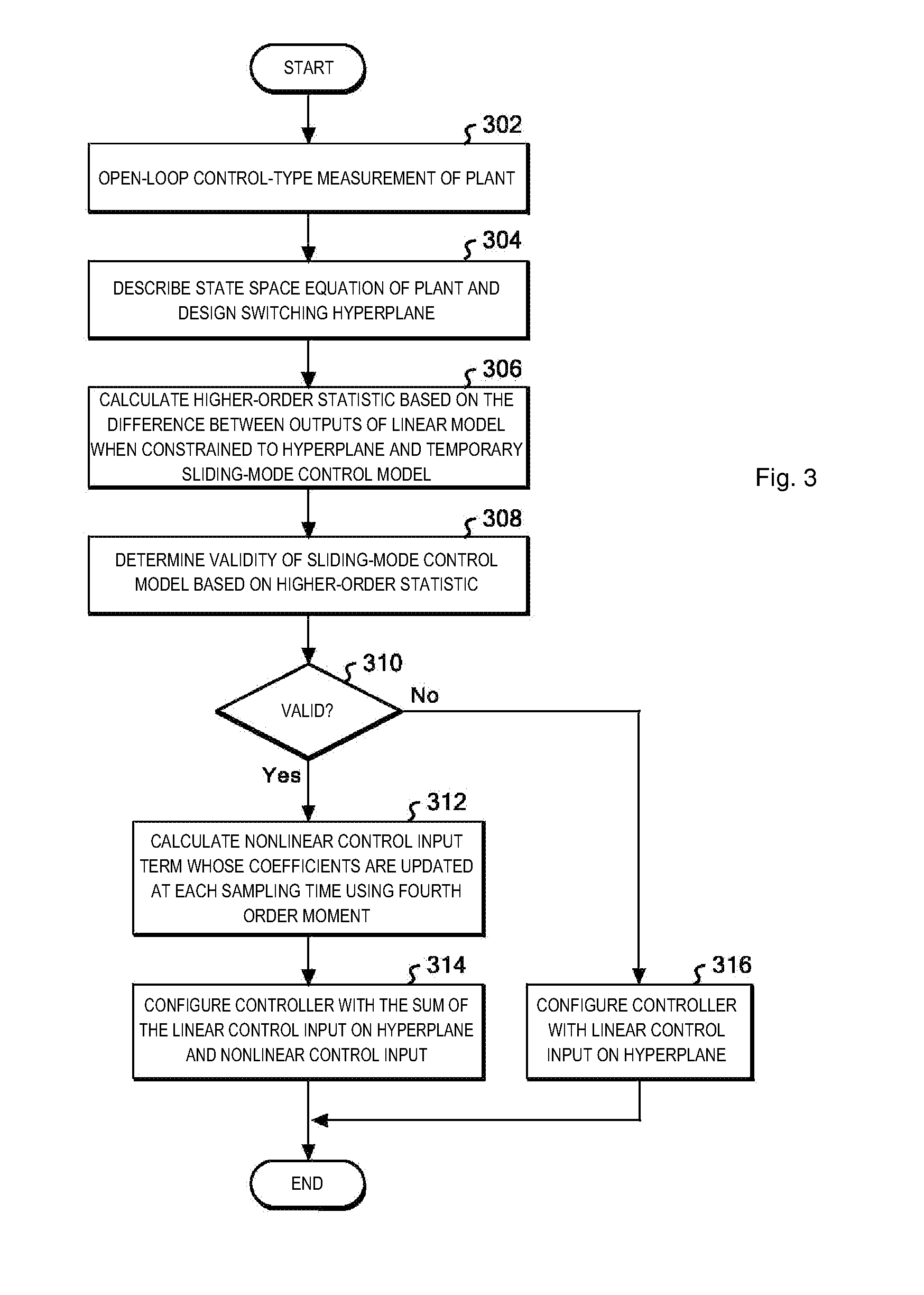
[0032]The basic principle of the invention is to provide a technique to automatically determine whether or not a sliding-mode control should be applied in a plant by using least amount of measured experimental data. Detailed description of the invention is made in combination with the following embodiments.

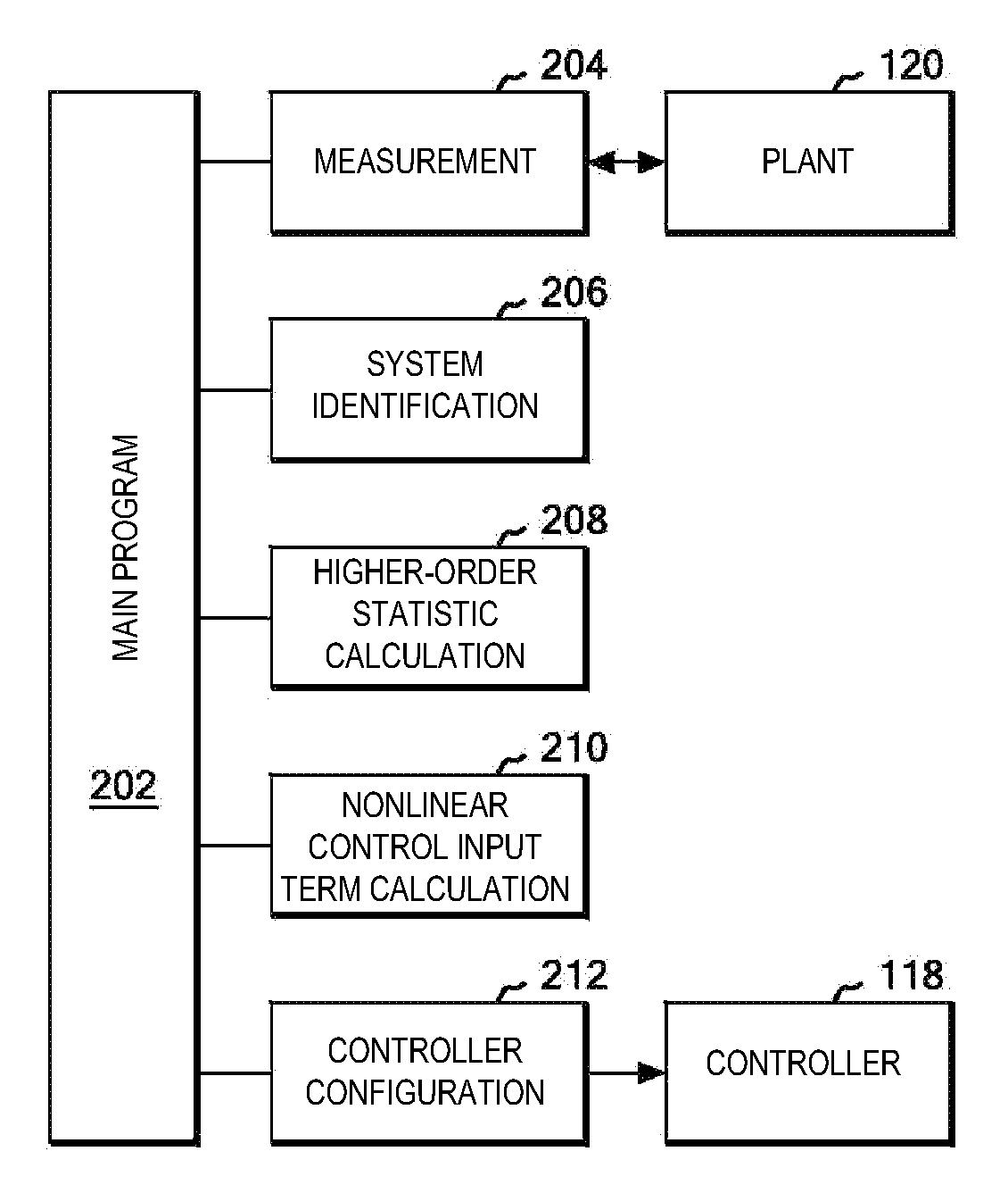
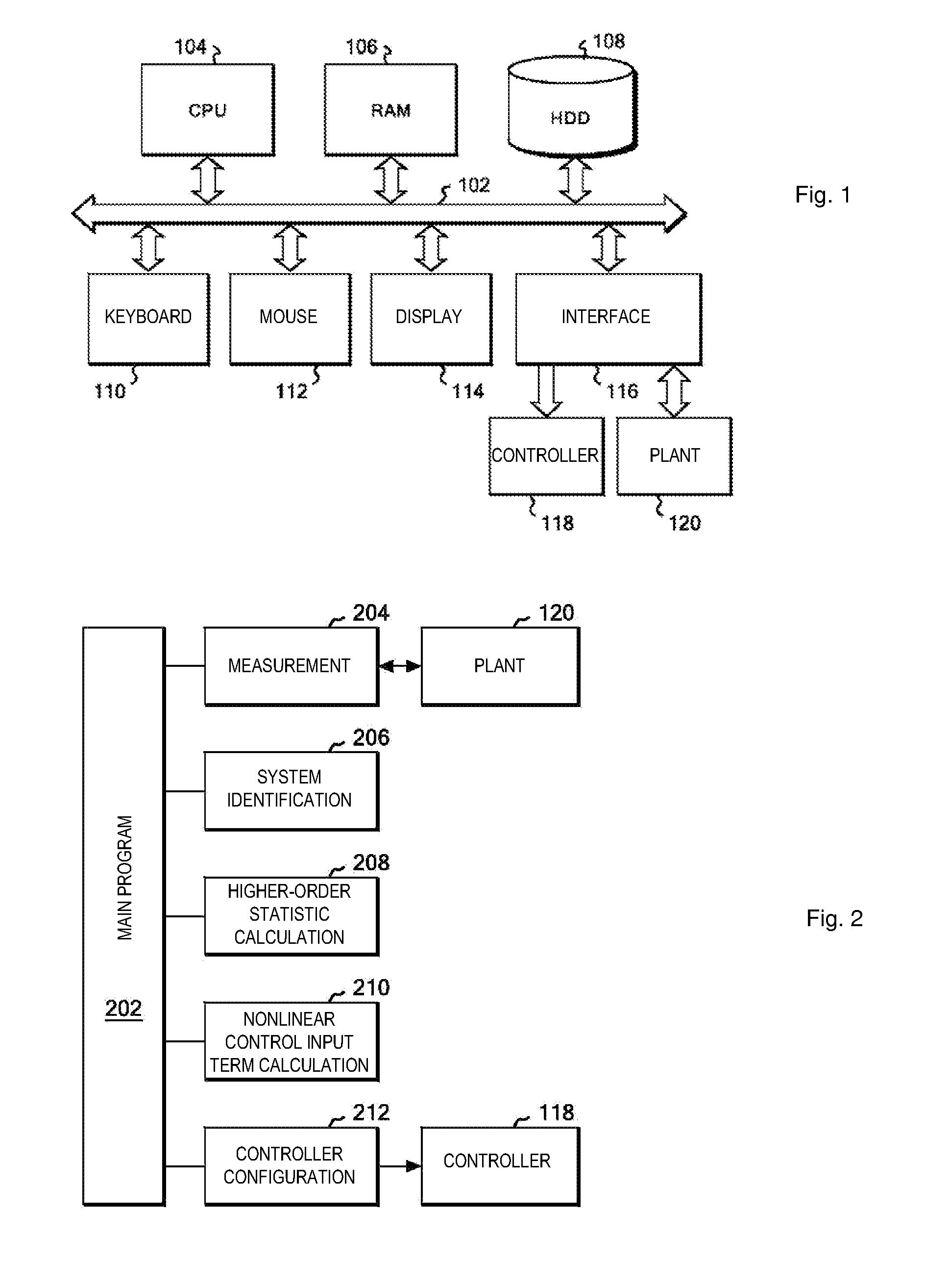
[0033]Referring to FIG. 1, a block diagram of hardware of a control computer for controlling a controller 118 according to an embodiment of the present invention is shown. In FIG. 1, a CPU 104, a main memory (RAM) 106, a hard disk drive (HDD) 108, a keyboa...


PUM


Abstract

Method, article of manufacture and system using minimum data to determine whether a sliding-mode control should be applied in a plant. First measure the plant in an open-loop control fashion, and using the measured data, describe a state equation of the plant by system identification and order determination methods. Then design a switching hyperplane for sliding-mode control. Next, calculate higher order statistics on the difference between an output of a linear model on the hyperplane and an output of the sliding-mode control model in the measured data; When any of the higher order moments is larger than a predetermined threshold, configure a controller as a sum of the linear control input term and the nonlinear control input term. If both higher-order moments are smaller than the threshold, then configure the controller using only a linear control input term.

Description

CROSS-REFERENCE TO RELATED APPLICATIONS[0001]This application claims priority under 35 U.S.C. §119 from Japanese Patent Application No. 2010-267280 filed Nov. 30, 2010, the entire contents of which are incorporated herein by reference.BACKGROUND OF THE INVENTION[0002]1. Field of the Invention[0003]The present invention relates to a sliding-mode control scheme, and more particularly to a method, article of manufacture, and system for configuring a controller in the sliding-mode control scheme, including a technique to automatically determine whether or not a sliding-mode control should be applied from least minimum measured experimental data.[0004]2. Description of Related Art[0005]Conventionally, it is often the case that a controller is required to be sufficiently robust against non-linear characteristics and parameter variations / load variations included in a system. As one solution to cope with such requirement, a sliding-mode control (SMC) has been widely used. The SMC causes the...

Claims


Application Information

Patent Timeline
IPC IPC(8): G05B13/02
CPCG05B13/0205G05B2219/42352G05B2219/42343
Inventor SHIMIZU, JUNYA
Owner IBM CORP
Learn More