Eureka AIR delivers breakthrough ideas for toughest innovation challenges, trusted by R&D personnel around the world.

Crane apparatus

a crane and apparatus technology, applied in the direction of cranes, etc., can solve the problems of complicated selection of telescopic patterns and long period of time for selecting telescopic patterns, and achieve the effect of maximizing the net rated load, and minimizing the period of tim

Active Publication Date: 2012-06-07
TADANO LTD
View PDF9 Cites 6 Cited by
  • Summary
  • Abstract
  • Description
  • Claims
  • Application Information

AI Technical Summary

Benefits of technology

[0007]It is therefore, an object of the present invention to provide a crane apparatus being capable of selecting telescopic patterns of a telescopic boom for a short period of time without time-consuming process.
[0009]The feature recited in claim 2 of the present invention is that when there are a plurality of telescopic patterns that allow the crane operation under the condition inputted to the condition input part, the telescopic pattern selecting part selects a telescopic pattern that minimizes a period of time for telescopic motion changing from a previous telescopic pattern. The feature recited in claim 3 of the present invention is that the condition input part can receive, as input, conditions for a plurality of crane operations and an order of the crane operations; and when there are a plurality of telescopic patterns of the telescopic boom that allow the crane operation under each condition inputted from the condition input part, the telescopic pattern selecting part selects each telescopic pattern that minimizes a period of time for entire telescopic motion of the telescopic boom changing from a telescopic pattern before a telescopic motion to a telescopic pattern of a last crane operation. The feature recited in claim 4 of the present invention is that when there are a plurality of telescopic patterns of the telescopic boom that allow the crane operation under the condition inputted to the condition input part, the telescopic pattern selecting part selects a telescopic pattern that maximizes a net rated load.
[0010]With the feature recited in claim 1 of the present invention, a telescopic pattern that allows a crane operation is selected from among a plurality of telescopic patterns by inputting a predetermined condition, which is easy operation. By this means, it is possible to improve operational efficiency.
[0011]With the feature recited in claim 2 of the present invention, when a plurality of telescopic patterns match the condition inputted to a condition input part, a telescopic pattern is selected to minimize a period of time for telescopic motion changing from the previous telescopic pattern. By this means, it is possible to further improve operational efficiency. With the feature recited in claim 3 of the present invention, when a plurality of telescopic patterns match each condition inputted to the condition input part, a telescopic pattern of the telescopic boom is selected for each condition to minimize a period of time required for telescopic motion for a plurality of crane operations. By this means, it is possible to further improve operational efficiency. With the feature recited in claim 4 of the present invention, when a plurality of telescopic patterns match the condition inputted to the condition input part, the telescopic boom can suspend goods, in a telescopic pattern having a substantially greater net rated load than the weight of the suspended goods. By this means, it is possible to improve safety.

Problems solved by technology

The operator has to select an optimum telescopic pattern from among thirty or more telescopic patterns for each crane operation, and consumes a long period of time to select a telescopic pattern.
Particularly, when consecutively performing a plurality of crane operations, the operator has to select respective patterns for the crane operations taking into account the order of the crane operations, and therefore selection of telescopic patterns becomes complicated.

Method used


Image

  • Crane apparatus
  • Crane apparatus
  • Crane apparatus

Examples


Embodiment Construction

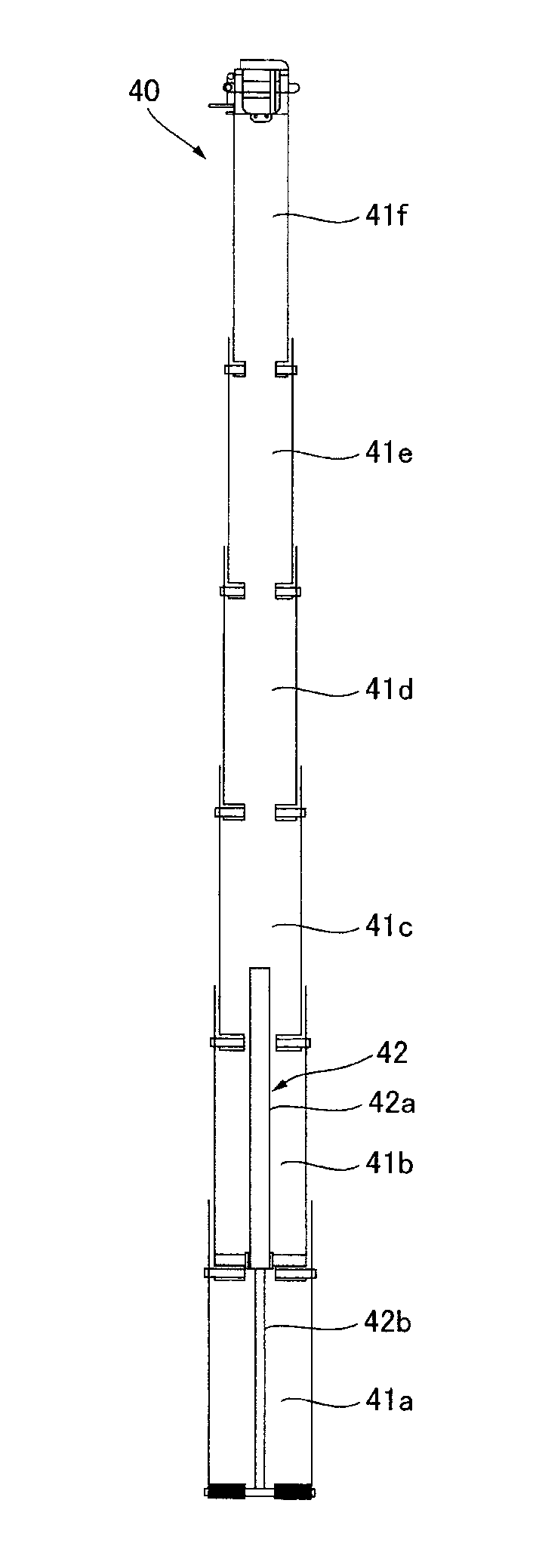
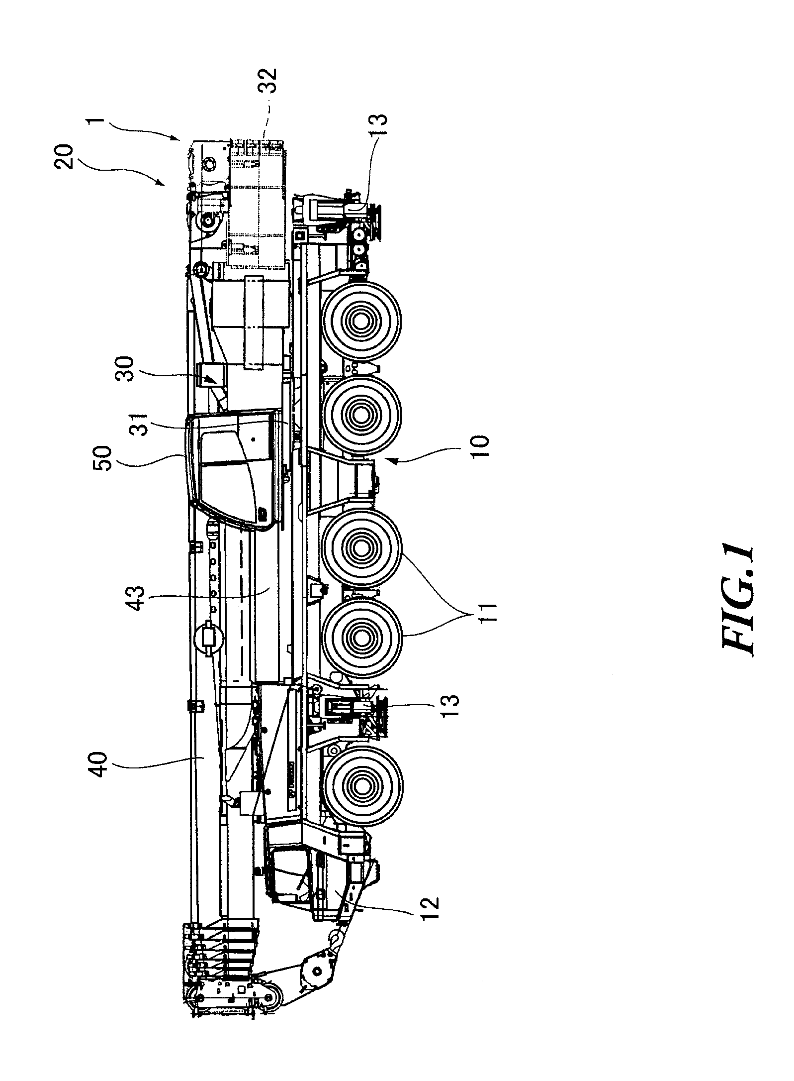
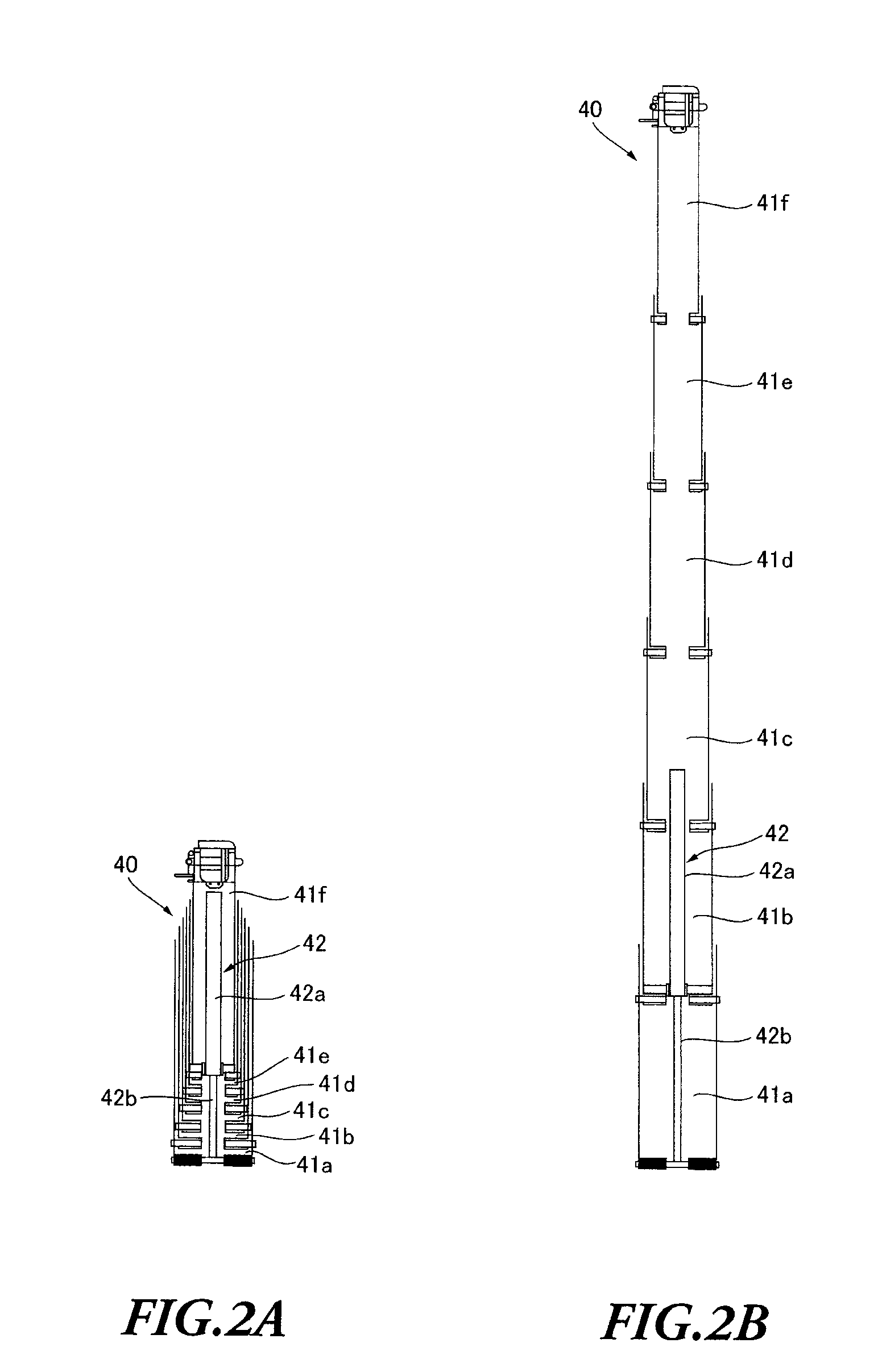
[0018]FIG. 1 to FIG. 6 show one embodiment of the present invention. With the present embodiment, a mobile crane adopting the crane apparatus of the present invention, will be described.

[0019]A mobile crane 1 includes a vehicle 10 for running and a crane apparatus 20, as shown in FIG. 1.

[0020]The vehicle 10 has a plurality of pairs of wheels 11 on both the left and right sides in the longitudinal direction, and runs by an engine as power source. A vehicle cabin 12 is provided in the front part of the vehicle 10, where operation for running of the vehicle 10 is performed. In addition, outriggers 13 are provided in the front part and back part of the vehicle 10 on both the left and right sides to prevent the vehicle 10 from falling down and stably support the vehicle 10 during a crane operation. When being used, each outrigger 13 is extended downward by a jack cylinder to contact the ground at the bottom.

[0021]The crane apparatus 20 includes a swivel base 30 pivotably provided in the ...


PUM


Abstract

A crane apparatus includes: a telescopic boom including a plurality of boom members, the telescopic boom performing telescopic motion by moving the plurality of boom members one by one using one telescopic cylinder; a condition input part configured to receive, as input, a condition for a crane operation including at least a weight of goods suspended by the telescopic boom, a height to which suspended goods are lifted, and a moving radius of the suspended goods; and a telescopic pattern selecting part configured to select a telescopic pattern that allows the crane operation under the condition inputted to the condition input part.

Description

CROSS REFERENCE TO RELATED APPLICATIONS[0001]This application claims priority of Japanese Patent Application No. 2010-272814 filed on Dec. 7, 2010. The contents of this application are incorporated herein by reference in their entirety.BACKGROUND[0002]1. Field of the Invention[0003]The present invention relates to a crane apparatus having a telescopic boom composed of a plurality of boom members. These boom members are telescopically configured, and the telescopic boom expands and contracts by moving the telescopic members one by one using one telescopic cylinder.[0004]2. Description of the Related Art[0005]Conventionally, as this sort of crane apparatuses, one has been known that includes a telescopic boom composed of a plurality of boom members, where the telescopic boom performs telescopic motion by moving these boom members one by one using one telescopic cylinder (see, for example, Japanese Patent Application Laid-Open Publication No. 2002-332194.SUMMARY[0006]If a crane apparat...

Claims


Application Information

Patent Timeline
Patent Type & Authority Applications(United States)
IPC IPC(8): B66C23/04
CPCB66C23/905B66C23/705
Inventor KAMEYAMA, YASUSHI
Owner TADANO LTD
Why Eureka
Eureka Blog
Learn More