Radiation imaging apparatus

Inactive Publication Date: 2012-06-07
CANON KK
View PDF2 Cites 8 Cited by
  • Summary
  • Abstract
  • Description
  • Claims
  • Application Information

AI Technical Summary

Benefits of technology

[0012]According to an aspect of the present invention, there is provided a radiation imaging apparatus capable of housing a radiation detection unit configured to detect radiation. The radiation imaging apparatus includes first cooling means configured to cool a first heat generation portion of the radiation detection unit housed in the radiation imaging apparatus by a cooling medium in the radiation imaging apparatus, second cooling means configured to cool a second heat generation portion of the radiation detection unit housed in the radiation imaging unit, which is larger in amount of generated heat than the first heat generation portion, by the cooling medium, and a discharge port formed in a position nearer to the second heat generation portion than to the first heat generation portion and configured to discharge the cooling medium.

Problems solved by technology

To meet such requirements, a heat generation problem concerning malfunctions or lifetimes of electronic components cannot be avoided, necessitating an efficient heat radiation unit.
In many cases, the temperature difference in the radiation imaging apparatus adversely affects an imaging process.
When a temperature difference occurs between the photoelectric conversion elements in the radiation imaging apparatus, a dark current varies from one photoelectric conversion to the other, causing a captured radiation image to be non-uniform.
A temperature distribution in the radiation imaging apparatus greatly affects the quality of a captured radiation image.
Consequently, the temperature distribution in the radiation imaging apparatus becomes non-uniform, adversely affecting the quality of a captured radiation image.
If a discharge port for discharging the heated air from the radiation imaging apparatus is formed in an inappropriate position, an unexpected flow of air occurs in the radiation imaging apparatus, probably causing the heated air to heat the electronic components in the radiation imaging apparatus.
Particularly, if a plurality of discharge ports is provided in the radiation imaging apparatus, external air frequently flows in and out, thus disabling prediction of a flow of air in the radiation imaging apparatus.
However, neither of the techniques gives any consideration to the flow of a cooling medium in the radiation imaging apparatus during capturing of a radiation moving image and, hence, both the techniques are unable to solve the problems caused by the temperature difference.

Method used


Image

  • Radiation imaging apparatus
  • Radiation imaging apparatus
  • Radiation imaging apparatus

Examples


Embodiment Construction

[0031]Various exemplary embodiments, features, and aspects of the invention will be described in detail below with reference to the drawings.

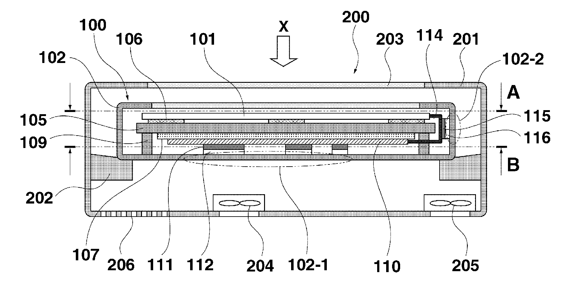
[0032]A radiation imaging apparatus of a radiation imaging apparatus system according to a first exemplary embodiment of the present invention will be described. The radiation imaging apparatus synchronizes with a radiation generation apparatus in the radiation imaging apparatus system, and acquires a captured radiation image by detecting radiation transmitted through an object. Hereinafter, a configuration of the radiation imaging apparatus is described.

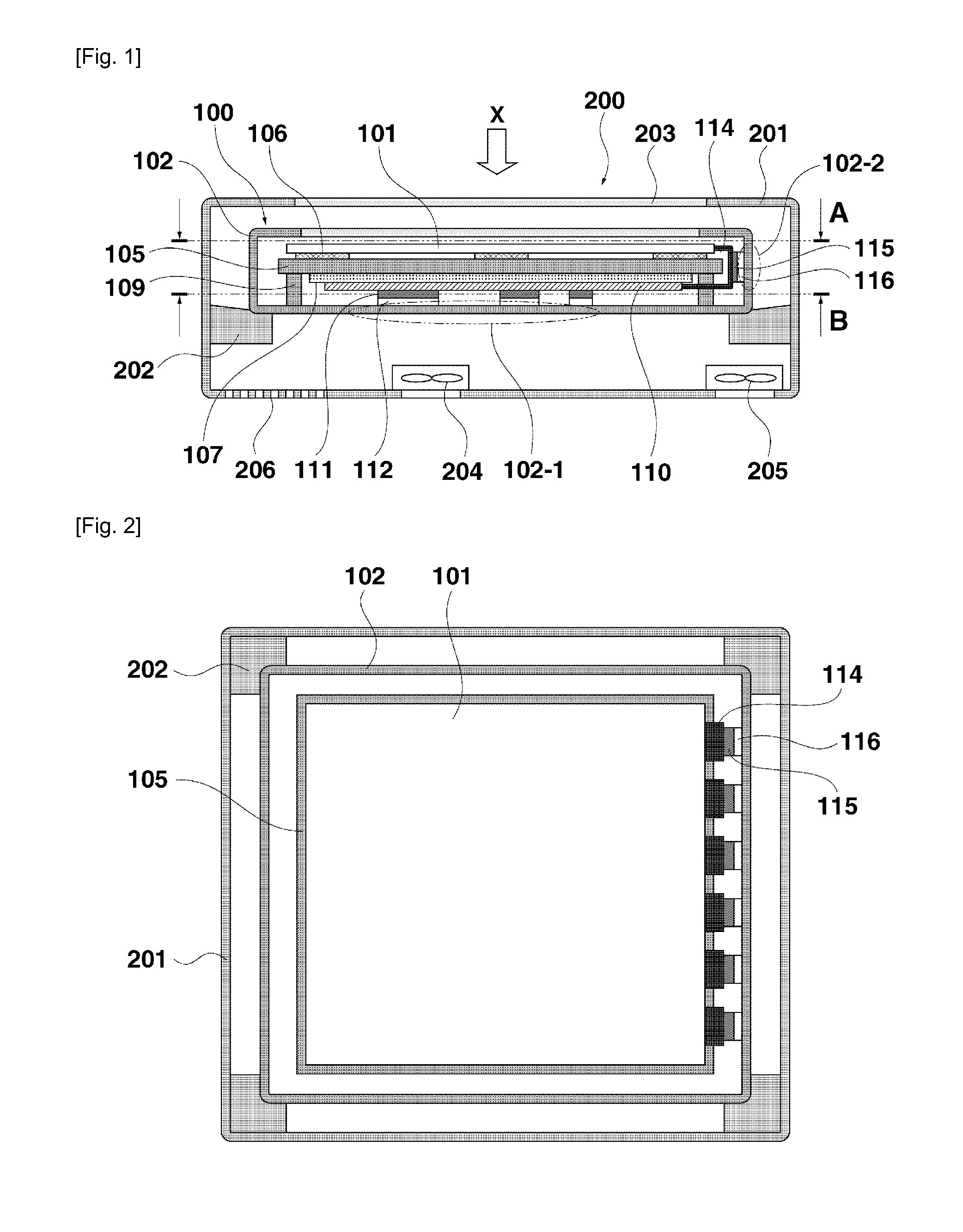
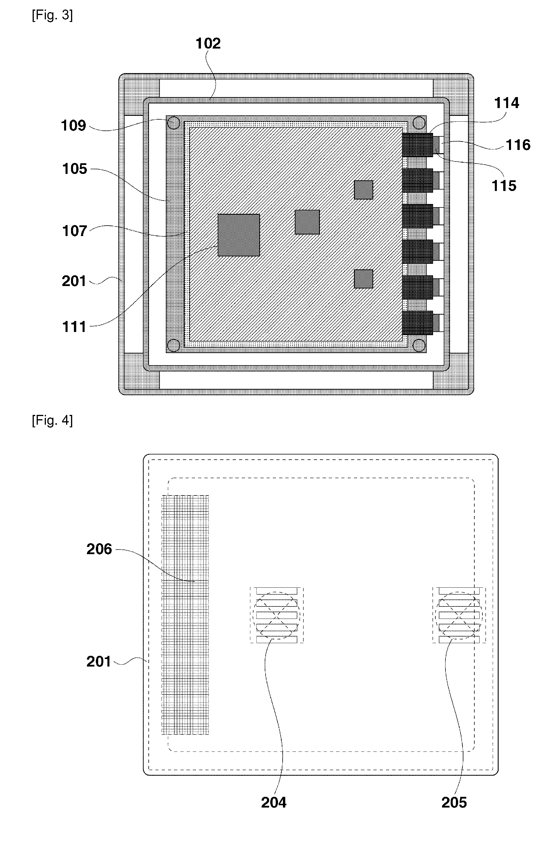
[0033]FIG. 1 is a sectional view of the radiation imaging apparatus along a plane perpendicular to a radiation-image receiving surface. FIG. 2 is a sectional view take along line A-A illustrated in FIG. 1. FIG. 3 is a sectional view taken along line B-B illustrated in FIG. 1. FIG. 4 is a rear view illustrating the radiation imaging apparatus.

[0034]The radiation imaging apparatus according to th...


PUM


Abstract

Provided is a radiation imaging apparatus capable of housing a radiation detection unit configured to detect radiation. The radiation imaging apparatus includes a first cooling unit configured to cool a first heat generation portion of the radiation detection unit housed in the radiation imaging apparatus by a cooling medium in the radiation imaging apparatus, a second cooling unit configured to cool a second heat generation portion of the radiation detection unit housed in the radiation imaging unit, which is larger in amount of generated heat than the first heat generation portion, by the cooling medium, and a discharge port formed in a position nearer to the second heat generation portion than to the first heat generation portion and configured to discharge the cooling medium.

Description

TECHNICAL FIELD[0001]The present invention relates to a radiation imaging apparatus that includes a radiation detection unit configured to acquire a radiation image by detecting radiation.BACKGROUND ART[0002]A radiation imaging apparatus system includes a radiation generation apparatus and a radiation imaging apparatus including a radiation detection unit, which are oppositely arranged to sandwich an object, and irradiates the object with radiation to acquire image information based on a signal output from the radiation detection unit. Mainly, the radiation imaging apparatus system is widely used in the fields of medical diagnosis and industrial nondestructive inspection.[0003]As a radiation imaging apparatus recently becoming widespread, there is a radiation flat-panel detector. The radiation flat-panel detector includes a combination of a photoelectric conversion panel arraying photoelectric conversion elements for converting visible light into electric charge and switching elemen...

Claims


Application Information

Patent Timeline
IPC IPC(8): G01T1/16G01T1/175
CPCG01T1/244H01L27/14618H01L2924/0002H01L2924/00
Inventor KATO, KATSUSHIKOBAYASHI, MASAAKIOMURA, SATORU
Owner CANON KK
Why Eureka
Try Eureka