Solid oxide fuel cell

Inactive Publication Date: 2011-05-12
MITSUBISHI MATERIALS CORP +1
View PDF1 Cites 6 Cited by
  • Summary
  • Abstract
  • Description
  • Claims
  • Application Information

AI Technical Summary

Benefits of technology

[0008]In view of the above, the present invention has been made, and an object of the present invention is to provide a solid oxide fuel cell which can efficiently operate by preventing an unreformed fuel gas from being supplied to a fuel electrode at start-up without requiring a storage chamber.
[0014]Therefore, at start-up, fuel gas can be supplied as is to the fuel gas supply line without the need to supply hydrogen and nitrogen from inlet ports, thereby preventing the entire apparatus from being excessively large by installing storage chambers for hydrogen and nitrogen.
[0015]Further, if the fuel cell stack is installed in the internal can body together with the start-up reformer and the like, and a heat insulating material is provided on an outer periphery of the internal can body, the temperature inside the internal can body efficiently increases at start-up by the heat released from the start-up heating means and an electrode reaction, which allows oxygen gas and reformed gas to be heated, and thus can shorten the time until power generation starts.
[0016]Furthermore, if the internal can body has a plurality of fuel cell stack groups made up of a plurality of fuel cell stacks disposed in the upward and downward directions, and the reformer is interposed between the fuel cell stack groups, the reformer is efficiently heated by the heat released from the fuel cell stack, and thus the present invention can prevent an excessive energy from being used to activate the fuel cell by shortening the time from activation to power generation start and reducing the operation time of the start-up heating means. In addition, the reformation reaction in the reformer is an endothermic reaction and thus, the difference in temperature distribution inside the internal can body can be reduced by installing the reformer at a position interposed between the fuel cell stacks having the highest temperature in the internal can body and the solid electrolyte layer can also be prevented from being broken due to thermal strain caused by a temperature difference.
[0017]In addition, if the start-up reformer is interposedly provided on a downstream side of the reformer on the fuel gas supply line, the start-up heating means for the start-up reformer can instantaneously adjust the heating temperature according to the change in temperature inside the internal can body. Likewise, if the start-up steam generator is interposedly provided on a downstream side of the steam generator on the steam supply line, the start-up heating means for the start-up steam generator can instantaneously adjust the heating temperature. Therefore, the fuel cell can be activated using minimum energy without excessively heating the reformed gas supplied to the fuel cell stack.
[0018]The start-up heating means installed in the internal can body can efficiently heat the start-up reformer and the start-up steam generator.

Problems solved by technology

However, the fuel cell has a problem in that at power generation, a high temperature atmosphere occurs around the fuel cell stack and thus the reformer can sufficiently reform the fuel gas by absorbing the surrounding heat, whereas at start-up, the reformer cannot perform a reformation reaction, namely, an endothermic reaction and thus an unreformed fuel gas is supplied to the fuel electrode layer.
Such a supply of an unreformed fuel gas to the fuel electrode layer does not contribute to power generation, but instead, a reducing gas such as hydrogen gas is not supplied and thus the fuel electrode layer is oxidized by oxygen in the air in the external atmosphere, thereby causing a problem that the fuel electrode layer is peeled off from the solid electrolyte layer by expansion and contraction thereof.
For this purpose, the fuel cell generally has storage chambers for nitrogen gas and hydrogen gas therein (see Patent Document 1), thereby causing a problem that the entire apparatus becomes excessively large.Patent Document 1: Japanese Patent Laid-Open No. 05-054901

Method used


Image

  • Solid oxide fuel cell
  • Solid oxide fuel cell
  • Solid oxide fuel cell

Examples


Embodiment Construction

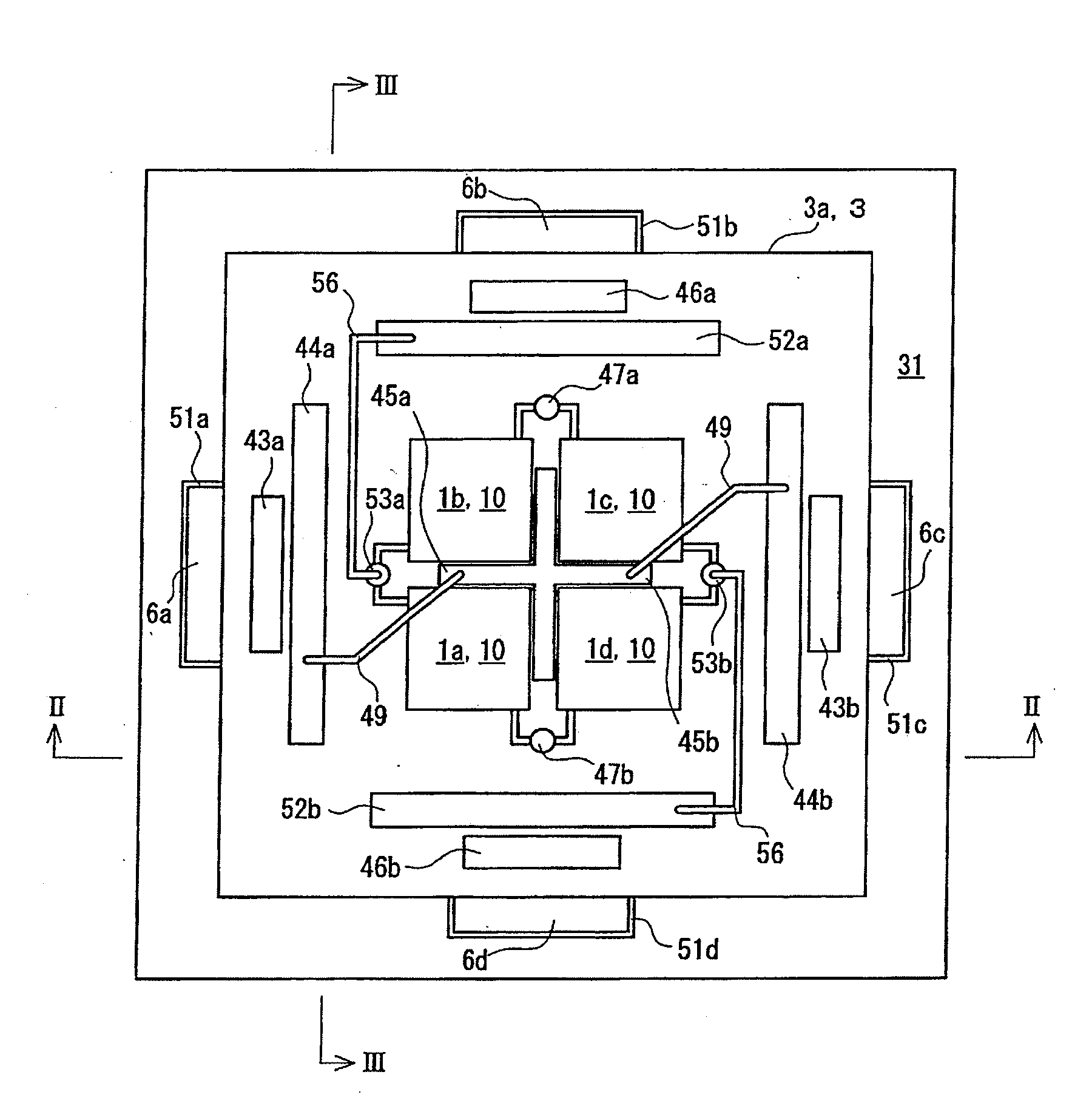
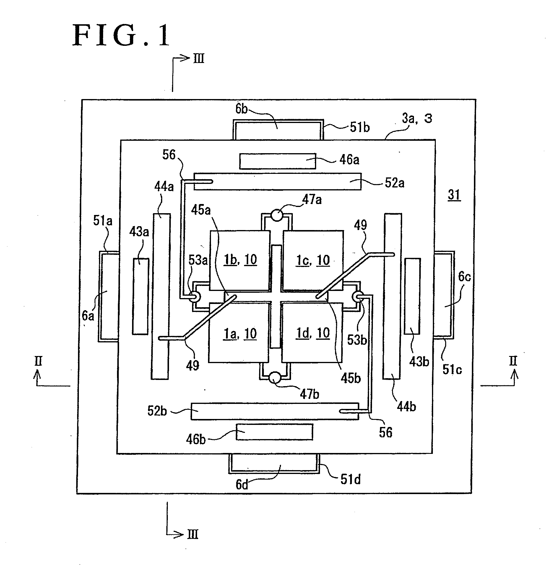
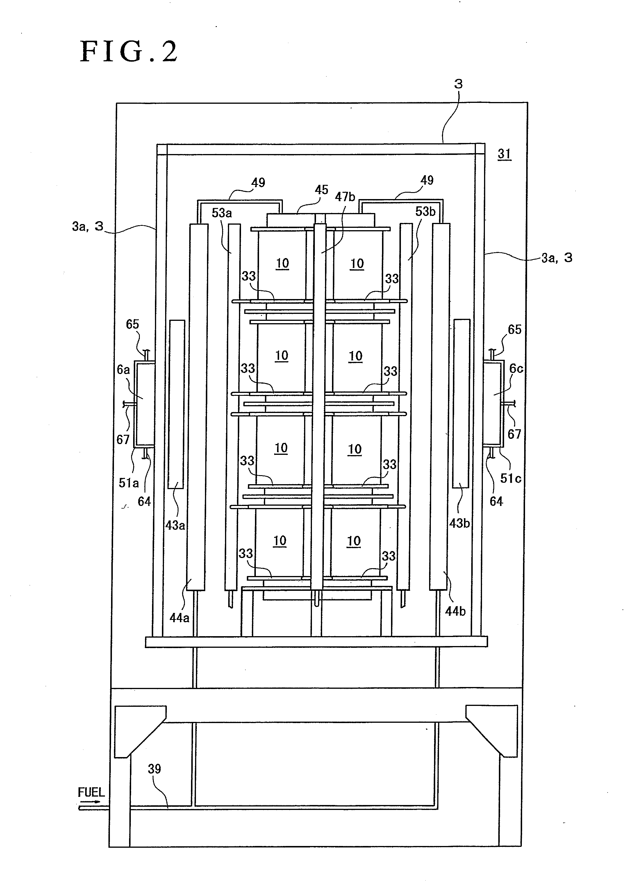
[0040]Hereinafter, embodiments of a flat plate solid oxide fuel cell according to the present invention will be described by referring to FIGS. 1 to 7B.

[0041]As illustrated in FIG. 5, a fuel cell according to the present embodiment is configured to have a fuel cell stack 10 which has an external appearance of a substantially rectangular columnar shape and laminates a plurality of power generation cells 16, which includes a fuel electrode layer 12 disposed on one surface of a solid electrolyte layer 11 and an air electrode layer (oxidant electrode layer) 13 disposed on the other surface thereof, by interposing a separator 2 between the power generation cells.

[0042]In addition, a fuel electrode current collector 14 is interposed between the fuel electrode layer 12 and the separator 2 of the power generation cell 16 and an air electrode current collector 15 is interposed between the air electrode layer 13 and the separator 2.

[0043]Here, the solid electrolyte layer 11 is formed into a d...


PUM


Abstract

An object of the present invention is to provide a fuel cell which prevents an unreformed fuel gas from being supplied to a fuel electrode at start-up without requiring a storage chamber for hydrogen gas and the like. In order to achieve this object, the fuel cell includes: a fuel cell stack (10) which laminates a power generation cell (16), which includes a fuel electrode layer (12), an oxidant electrode layer (13), and a solid electrolyte layer (11) sandwiched therebetween, by interposing a separator (2) between the power generation cells (16); a fuel gas supply line (40) which interposedly provides a reformer (45) supplying a reformed gas to the stacks (10); and a steam supply line (60) which interposedly provides a steam generator (41) supplying steam to an upstream side of the reformer on the fuel gas supply line, wherein start-up reformers (46a) and (46b) are interposedly provided on a downstream side of a connection portion to the steam supply line on the fuel gas supply line; start-up steam generators (43a) and (43b) are interposedly provided on the steam supply line; and the start-up reformer and the start-up steam generator are installed at a position facing start-up heating means (6a) to (6d) which operate at start-up.

Description

TECHNICAL FIELD[0001]The present invention relates to a solid oxide fuel cell having a power generation cell which includes a fuel electrode layer, an air electrode layer, and a solid electrolyte layer sandwiched therebetween.BACKGROUND ART[0002]In recent year, a fuel cell which directly converts the chemical energy of fuel to electrical energy has gained attention as a highly efficient and clean power generating apparatus. The fuel cell has a fuel cell stack which laminates a power generation cell, which includes an air electrode layer (cathode), a fuel electrode layer (anode), and a solid electrolyte layer which is made of an oxide ion conductor and is sandwiched between the air electrode layer and the fuel electrode layer, by interposing a separator between the power generation cells.[0003]At power generation, an oxidant (oxygen) is supplied as a reactant gas to an air electrode layer side, and a reformed gas (H2, CO, CO2, H2O, etc.) obtained by reforming a fuel gas (town gas con...

Claims


Application Information

Patent Timeline
IPC IPC(8): H01M8/04H01M8/06
CPCH01M8/04268H01M8/241Y02E60/50Y02E60/525H01M2008/1293C01B2203/0205C01B2203/066C01B2203/0805H01M8/0625C01B3/34H01M8/2483H01M8/04225H01M8/2432H01M8/2425
Inventor SATO, MOTOKIMIYAZAWA, TAKASHIMURAKAMI, NAOYA
Owner MITSUBISHI MATERIALS CORP
Why Eureka
Try Eureka