
Power Conductor Monitoring Device and Method of Calibration

a monitoring device and conductor technology, applied in the direction of fault location, line-transmission details, instruments, etc., can solve the problems of significant problems, temporary power loss, and costing the utility company money

Active Publication Date: 2012-06-07
SENTIENT TECH HLDG LLC
View PDF2 Cites 52 Cited by
  • Summary
  • Abstract
  • Description
  • Claims
  • Application Information

AI Technical Summary

Problems solved by technology

Typically, difficulties or faults within the distribution network are identified only after occurrences of “events.” These events may merely result in a temporary loss of power for a limited number of customers, but more significant problems may occur.
This is important to utility companies because power factors less than 1 indicate losses and inefficiencies in the distribution network, costing the utility companies money.
The non-isolated electrical connection and associated equipment is expensive and expensive to install.
Further it does not provide for an easily deployed solution in a wide range of locations along a distribution network.
However, these specialized monitoring systems have been unable to accurately measure changing voltage at the power lines from the surrounding electric field due to changes in weather, traffic, dirt buildup on the lines, construction of or placement of large objects near the power lines, etc.
Thus, utility companies must rely on measurement of power factor at electrical substations or remote expensive monitoring equipment, which does not facilitate identification of the specific location along a distribution system responsible for a reduced power factor.

Method used


Image

  • Power Conductor Monitoring Device and Method of Calibration
  • Power Conductor Monitoring Device and Method of Calibration
  • Power Conductor Monitoring Device and Method of Calibration

Examples


Embodiment Construction

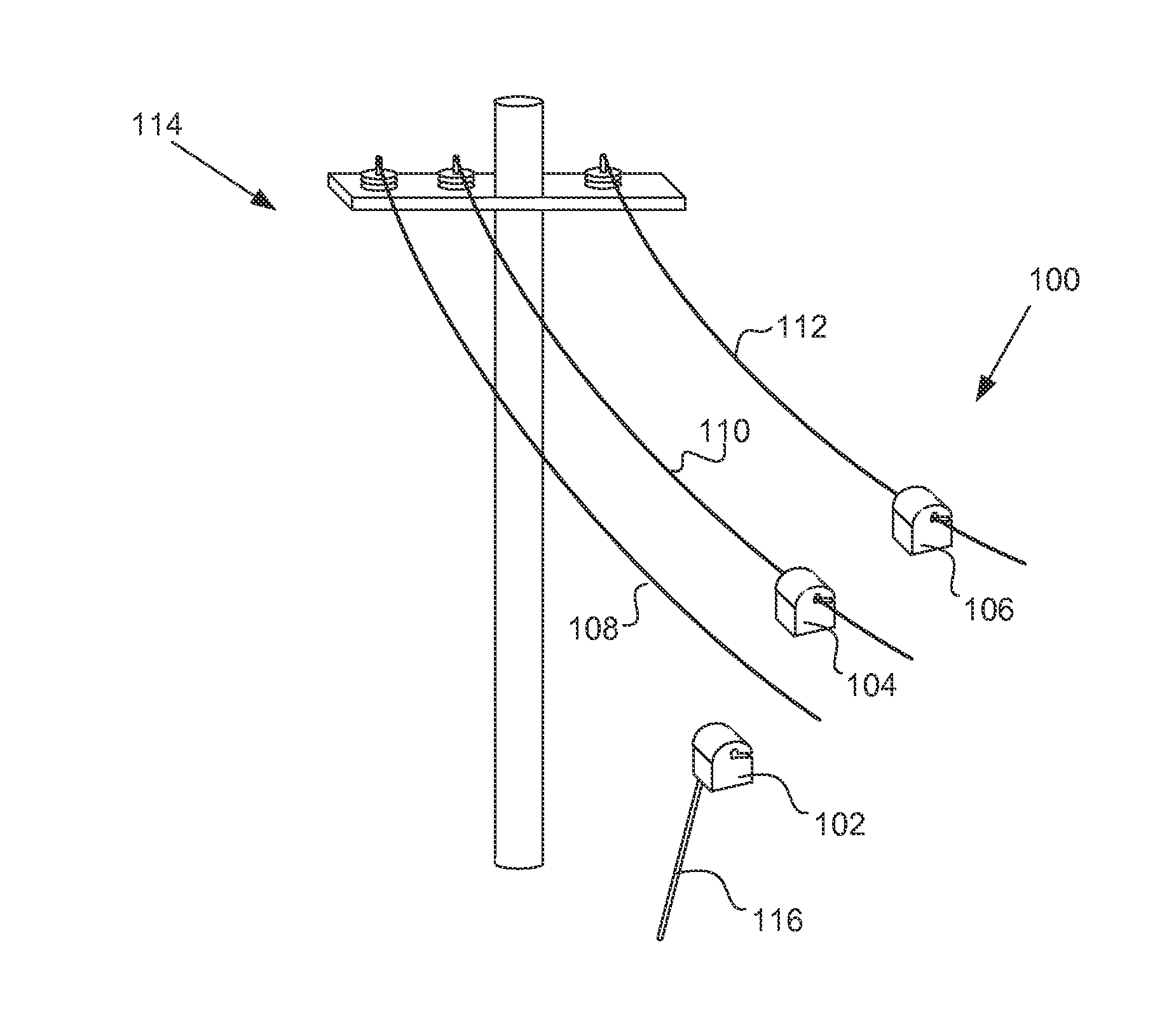
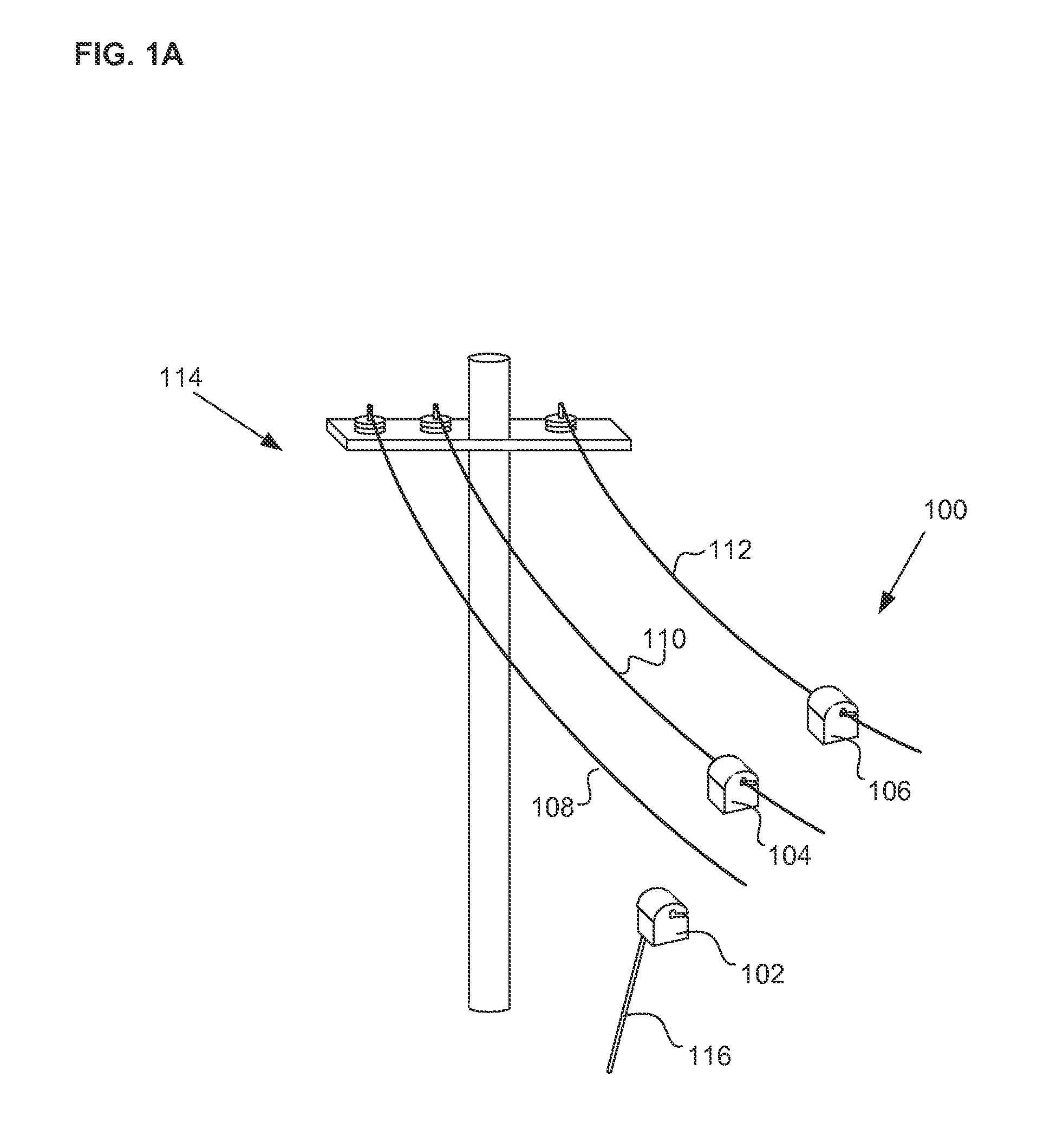
[0025]Power line monitoring devices and systems described herein are configured to measure the currents and voltages of power grid distribution networks. Referring to FIG. 1A, monitoring system 100 comprises monitoring devices 102, 104, and 106 mounted to power line conductors 108, 110, and 112, respectively, of power distribution network 114. The power distribution network can be a three phase AC network, or alternatively, a single-phase network, for example. The power distribution network can be any type of network, such as a 60 Hz North American network, or alternatively, a 50 Hz network such as is found in Europe and Asia, for example. Power distribution networks, such as in the United States, typically operate at a medium voltage (e.g., 4 kV to 46 kV or higher) to reduce the energy lost during transmission over long distances. The monitoring devices can also be used on high voltage “transmission lines” or conductors that operate at voltages higher than 46 kV.

[0026]Monitoring de...


PUM


Abstract

A power distribution monitoring system is provided that can include a number of features. The system can include a plurality of monitoring devices configured to attach to individual conductors on a power grid distribution network. In some embodiments, a monitoring device is disposed on each conductor of a three-phase network. The monitoring devices can be configured to measure and monitor, among other things, current and electric-field on the conductors. Methods of calibrating the monitoring devices to accurately measure electric-field are also provided. In one embodiment, a first monitoring device on a first conductor can transmit a calibration pulse to a second monitoring device on a second conductor. The second monitoring device can determine a degradation of the calibration pulse, and use that degradation to calibrate electric-field measurements around the conductor.

Description

CROSS REFERENCE TO RELATED APPLICATIONS[0001]This application claims the benefit under 35 U.S.C. 119 of U.S. Provisional Patent Application No. 61 / 420,247, filed Dec. 6, 2010, titled “Power Line Monitoring Device and Method of Calibration”, which application is incorporated by reference as if fully set forth herein.INCORPORATION BY REFERENCE[0002]All publications and patent applications mentioned in this specification are herein incorporated by reference to the same extent as if each individual publication or patent application was specifically and individually indicated to be incorporated by reference.FIELD OF THE INVENTION[0003]The present invention generally relates to power distribution networks. More specifically, the present invention relates to monitoring of power distribution systems.BACKGROUND OF THE INVENTION[0004]In providing power to customers, electrical power utility companies employ a power grid distribution network that includes distribution-line-conductors (which ar...

Claims


Application Information

Patent Timeline
IPC IPC(8): G01R31/02G01R23/02G01R19/00
CPCG01R29/08Y04S10/522G01R35/04G01R31/086Y04S10/52
Inventor PARSONS, MARK A.
Owner SENTIENT TECH HLDG LLC
Learn More