This helps you quickly interpret patents by identifying the three key elements:
Problems solved by technology
Method used
Benefits of technology
Benefits of technology
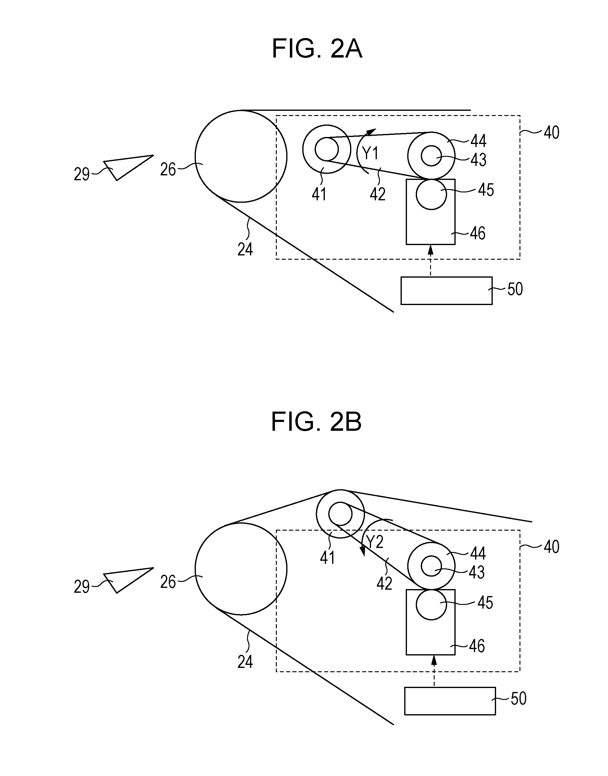
[0009]The present invention can prevent a conveyance error of a recording material to be conveyed to a guide for guiding the recording material after separation, which may occur when a push-up member is used to separate the recording material.
Problems solved by technology
However, if the recording material has a low rigidity, the curvature of a separation roller, serving as a separation belt-stretching member, around which the transfer belt is stretched and the rigidity of the recording material itself are not enough to separate the recording material from the transfer belt.
In such a case, the recording material is adhered to the transfer belt at a position of the separation roller, resulting in a separation error.
Although unevenness can be formed at the separation position of the transfer belt in this configuration, the transfer belt is constantly and locally subjected to a large tension.
As a result, the transfer belt is locally worn away, causing variations in the resistance and making the transfer characteristics unstable.
Thus, unevenness is formed in the recording material, increasing the rigidity of the recording material during the separation process.
In this case, if the guide member for guiding the recording material separated from the belt is disposed so as to be flush with the belt surface that is not pushed up, a conveyance error of the recording material to be conveyed to the guide member may occur when the recording material is separated by a pushing-up operation.
Method used
Image
Click on the blue label to locate the original text in one second.
Reading with bidirectional positioning of images and text.
Examples
first embodiment
Image Forming Apparatus
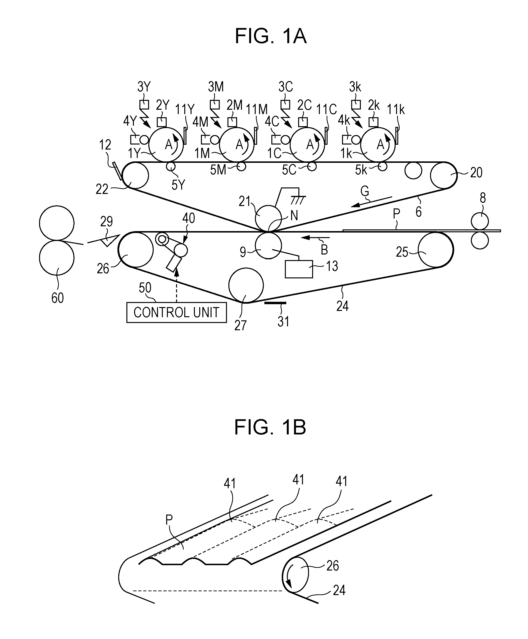
[0022]Referring to FIG. 1A, the configuration and operation of an image forming apparatus according to this embodiment will be described.
[0023]Photosensitive drums 1Y, 1M, 1C, and 1k serve as image bearing members and are rotated in the direction of arrow A. Charging units 2Y, 2M, 2C, and 2k uniformly charge the surfaces of the image bearing members 1Y, 1M, 1C, and 1k at a predetermined voltage. Exposure units 3Y, 3M, 3C, and 3k composed of laser beam scanners irradiate the charged surfaces of the photosensitive drums 1Y, 1M, 1C, and 1k with light, forming electrostatic latent images thereon. The laser beam scanners are switched on and off according to image information, forming electrostatic latent images corresponding to an image on the photosensitive drums 1Y, 1M, 1C, and 1k. Developing units 4Y, 4M, 4C, and 4k contain yellow (Y), magenta (M), cyan (C), and black (k) toners, respectively. The electrostatic latent images are developed as they pass through th...
second embodiment
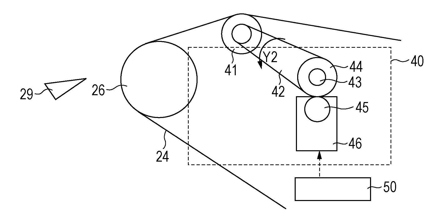
[0066]The description of the configuration common to the first embodiment will be omitted. The position of the recording material guide 29 is fixed in the first embodiment, whereas the tip of the recording material guide 29 is movable in this embodiment.
[0067]In this embodiment, the tip of the recording material guide 29 receives a driving force from a motor (not shown) and moves to a first position shown in FIG. 9 and to a second position below the first position in the perpendicular direction that is perpendicular to the surface of the transfer belt 24 not pushed up.
[0068]Reference numeral Zb1 denotes the distance between the upstream end, in the recording-material conveying direction, of the recording material guide 29 at the first position and the extension of the surface of the transfer belt 24 that is not pushed up. Herein, Zb1=4.6 mm, and, at the first position, the upstream end of the recording material guide 29 is on the same side as the separation belt-stretching roller 26...
PUM
Abstract
An upstream end of a guide surface of a recording material guide in the recording-material conveying direction is located on the same side as a separation belt-stretching roller with respect to an extension of the belt surface from the separation belt-stretching roller to a recessed portion formed in the belt surface by the separation assistance rollers.
Description
BACKGROUND OF THE INVENTION[0001]1. Field of the Invention[0002]The present invention relates to an image forming apparatus, such as a copier or a laser printer, which transfers a toner image formed on an image bearing member to a recording material using an electrophotography technique. More specifically, the present invention relates to an image forming apparatus having a transfer belt that transfers an image and conveys a recording material.[0003]2. Description of the Related Art[0004]In an electrophotographic apparatus in which a transfer belt stretched over a plurality of rollers carries and conveys a recording material, the recording material on the transfer belt is electrostatically attracted to the transfer belt after having passed through a transfer nip.[0005]However, if the recording material has a low rigidity, the curvature of a separation roller, serving as a separation belt-stretching member, around which the transfer belt is stretched and the rigidity of the recording...
Claims
Application Information
Patent Timeline
Application Date:The date an application was filed.
Publication Date:The date a patent or application was officially published.
First Publication Date:The earliest publication date of a patent with the same application number.
Issue Date:Publication date of the patent grant document.
PCT Entry Date:The Entry date of PCT National Phase.
Estimated Expiry Date:The statutory expiry date of a patent right according to the Patent Law, and it is the longest term of protection that the patent right can achieve without the termination of the patent right due to other reasons(Term extension factor has been taken into account ).
Invalid Date:Actual expiry date is based on effective date or publication date of legal transaction data of invalid patent.

