Interpretation of Real Time Compaction Monitoring Data Into Tubular Deformation Parameters and 3D Geometry

a technology of compaction monitoring and data analysis, applied in the direction of instruments, structural/machine measurement, force/torque/work measurement, etc., can solve the problems of tubular damage or even well failure, large stress, and both revenue generation and operation costs

Inactive Publication Date: 2012-06-07
BAKER HUGHES INC
View PDF8 Cites 37 Cited by
  • Summary
  • Abstract
  • Description
  • Claims
  • Application Information

AI Technical Summary

Problems solved by technology

These tubulars often encounter a large amount of stress, due to compaction, fault movement or subsidence, for example, which can lead to tubular damage or even to well failure.
Well failures significantly impact both revenue generation and operation costs for oil and gas production companies, often resulting in millions of dollars lost in repairing and replacing the wells.
Determining the deformation of a tubular under different stress distributions can be very complicated.
In many cases, due to the unknown internal and external forces involved, it is not realistic to use pre-developed geometric models to simulate a deformation.

Method used


Image

  • Interpretation of Real Time Compaction Monitoring Data Into Tubular Deformation Parameters and 3D Geometry
  • Interpretation of Real Time Compaction Monitoring Data Into Tubular Deformation Parameters and 3D Geometry
  • Interpretation of Real Time Compaction Monitoring Data Into Tubular Deformation Parameters and 3D Geometry

Examples


Embodiment Construction

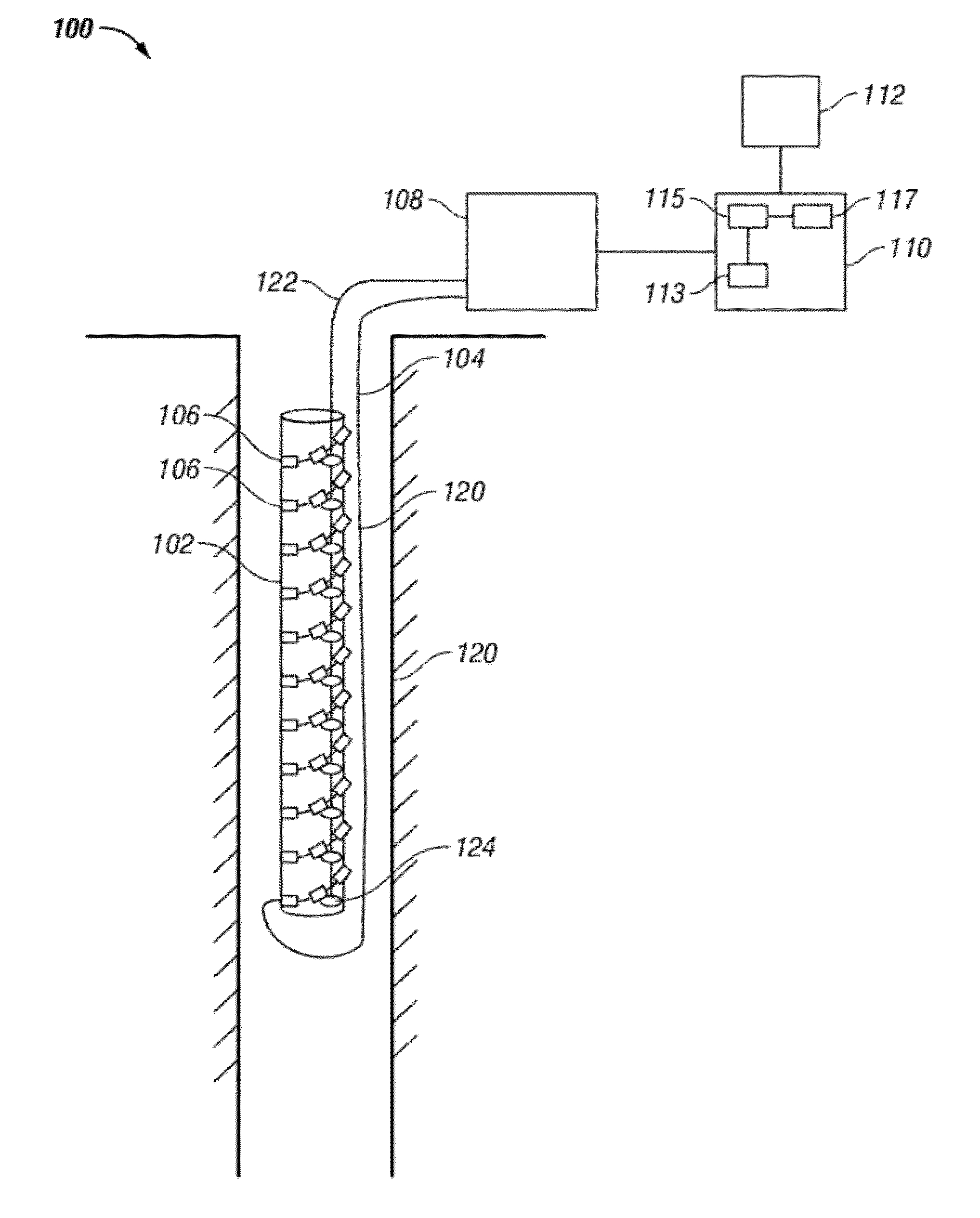
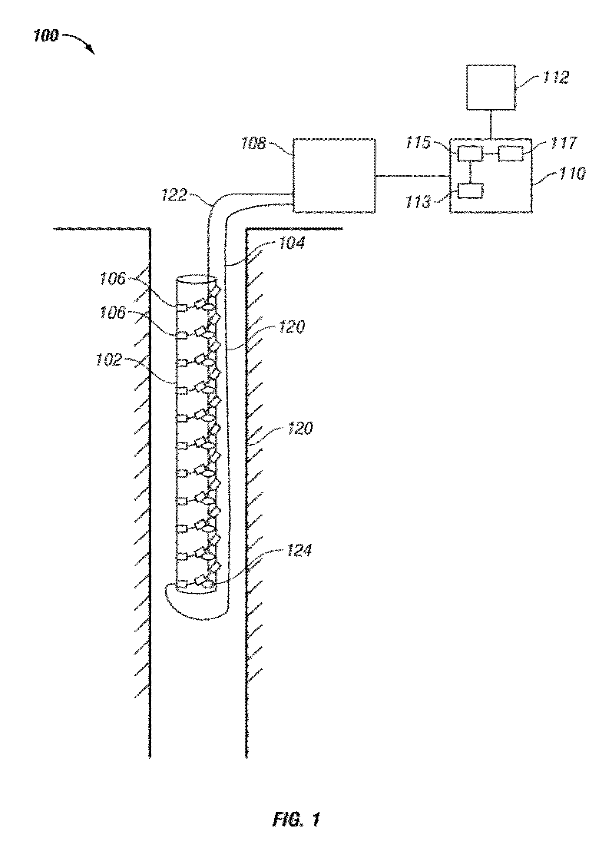
[0032]FIG. 1 shows an exemplary embodiment of a system 100 for determining a deformation of a tubular 102 disposed in a wellbore 120. The tubular may be any tubular typically used in a wellbore, such as a well casing or a drilling tubular, for example. In addition, the present disclosure is not limited to a tubular in a wellbore and may also be used on any exemplary member such as a casing, a sand screen, a subsea riser, an umbilical, a tubing, a pipeline, a cylindrical structure bearing a load and so forth. The exemplary member may undergo a variety of deformations. The exemplary member includes a plurality of sensors at various locations on the member. Each of the plurality of sensors obtains a measurement related to strain at the related location on the tubular. In various embodiments, the plurality of sensors may be Bragg grating sensors, Brillouin fiber optic sensors, electrical strain sensors, sensors along a fiber optic cable, or any other device for obtaining a strain measur...


PUM

PropertyMeasurementUnit
wavelength shiftaaaaaaaaaa
compression/tensionaaaaaaaaaa
spatial frequencyaaaaaaaaaa

Abstract

A method, apparatus and computer-readable medium for determining a deformation strain distribution of a member corresponding to a selected deformation mode is disclosed. Strain measurements are obtained at a plurality of sensors, wherein each strain measurement is related to a strain at a location of the member. A component of the strain related to a selected deformation mode for the obtained strain measurements is determined and a principal strain component and a secondary strain component for each of the determined components of the strain is determined. The determined principal strain component and secondary strain component are mapped to a surface of the member to determine the deformation strain distribution.

Description

CROSS REFERENCE TO RELATED APPLICATIONS[0001]The present application is related to Attorney Docket No. PRO4-49330-US, filed Dec. 3, 2010, Attorney Docket No. PRO4-49332-US, filed Dec. 3, 2010, Attorney Docket No. PRO4-50985-US, filed Dec. 3, 2010, Attorney Docket No. PRO4-51016-US, filed Dec. 3, 2010, and Attorney Docket No. PRO4-50984-US, filed Dec. 3, 2010, the contents of which are hereby incorporated herein by reference in their entirety.BACKGROUND OF THE DISCLOSURE[0002]1. Field of the Disclosure[0003]The present application is related to methods for determining deformations on a tubular in a wellbore.[0004]2. Description of the Related Art[0005]Tubulars are used in many stages of oil exploration and production, such as drilling operations, well completions and wireline logging operations. These tubulars often encounter a large amount of stress, due to compaction, fault movement or subsidence, for example, which can lead to tubular damage or even to well failure. Well failures ...

Claims


Application Information

Patent Timeline
Patent Type & Authority Applications(United States)
IPC IPC(8): G06F19/00G01L1/00
CPCG01L1/246G01M5/0025
Inventor CHEN, JIANFENGYANG, XUDONGTHIGPEN, BRIAN L.CHILDERS, BROOKS A.
Owner BAKER HUGHES INC
Why Eureka
Try Eureka