Support Structure of a Digital Device

a technology of supporting structure and digital device, which is applied in the direction of machine supports, instruments, other domestic objects, etc., can solve the problems of inconvenient user touch screen, easy to fall and easy to break the conventional digital device, so as to facilitate the use of convenience and convenience, and prevent the digital device from sliding from the user's hand. , the effect of enhancing the anti-slip

Inactive Publication Date: 2012-06-14
AIDMA ENTERPRISE
View PDF7 Cites 42 Cited by
  • Summary
  • Abstract
  • Description
  • Claims
  • Application Information

AI Technical Summary

Benefits of technology

[0007]The primary object of the present invention is to provide a supporting structure of a digital device of which the holding unit and the angle adjusting mechanism are fixed in a retaining manner, accordingly the holding unit is removed from the angle adjusting mechanism easily to be portable conveniently, and the hole of the tray member of the holding unit is grasped by the user's fingers to place the digital device securely and safely, preventing the digital device from sliding from the user's hand. Furthermore, the hole is applicable for various digital devices which are rotated horizontally or vertically. Also, the anti-slip cushion fixed in the four through orifices at four corners of the tray member matches with the protective pad to enhance anti-proof effect greatly.

Problems solved by technology

However, such a conventional digital device is easy to fall from a user's hand to be broken, when the user touches its screen carelessly.
Besides, the digital device has to be held by the user's hand, therefore the user will feel uncomfortable after operating it for a long period of time.
When the digital device is put on a desk, the user can not view the screen clearly because of a reflected light from the screen, and it is inconvenient for the user to touch the screen.
If the digital device contacts with the desk or an object at a tilted angle, it slides easily and can not be adjusted toward a preferred operating angle, operating troublesomely.

Method used


Image

  • Support Structure of a Digital Device
  • Support Structure of a Digital Device
  • Support Structure of a Digital Device

Examples


first embodiment

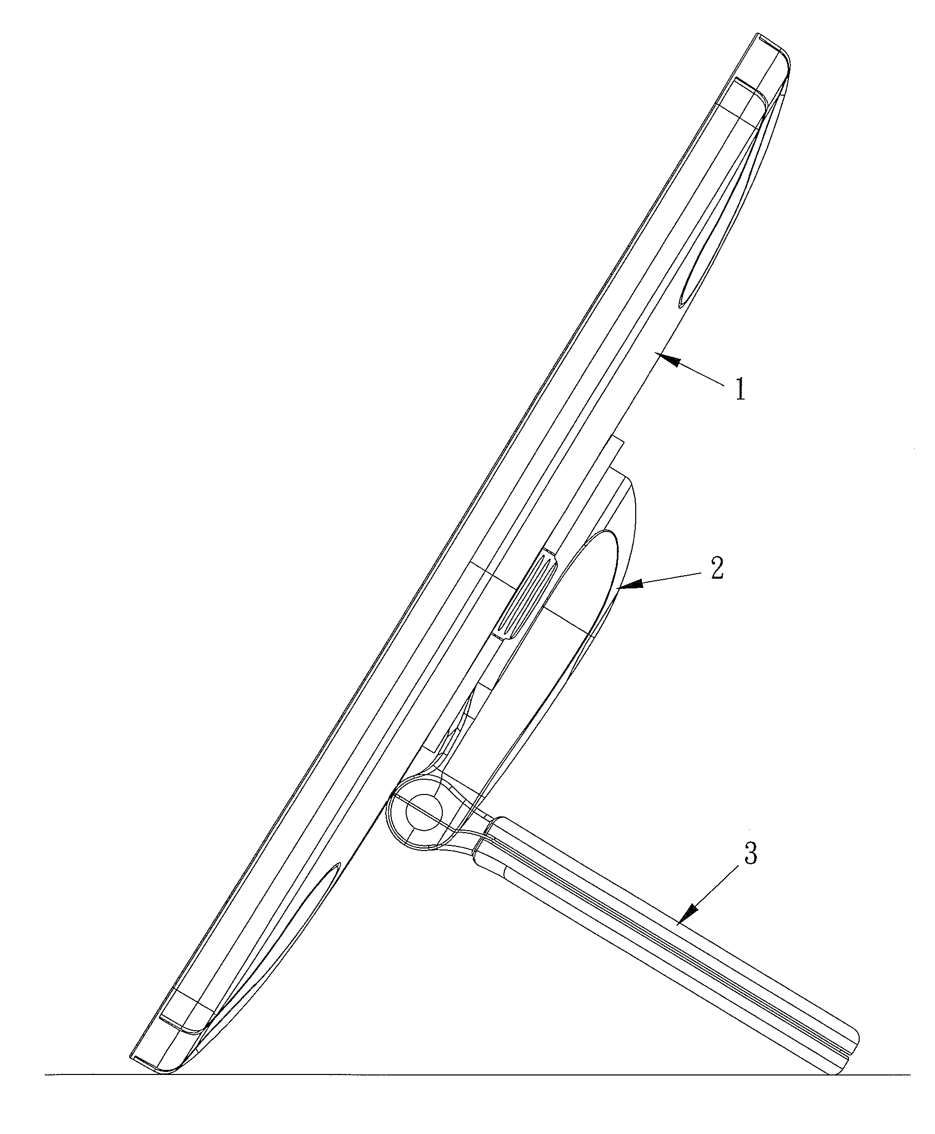
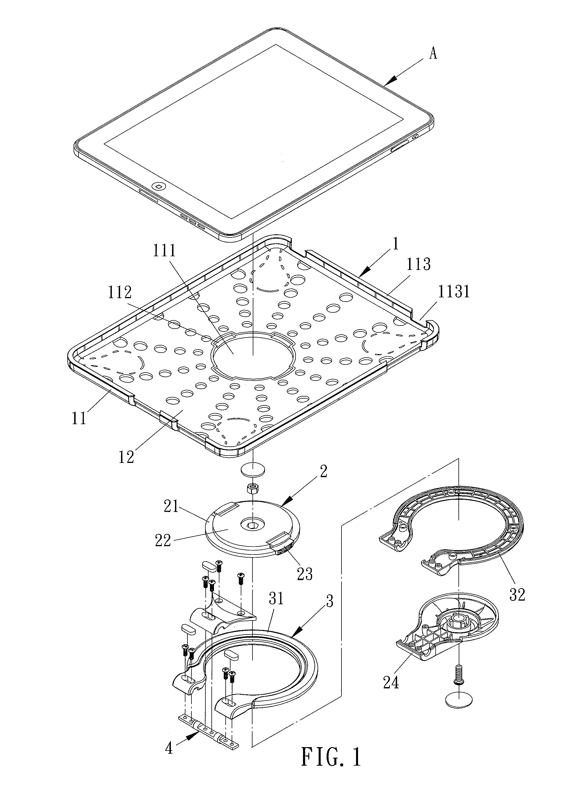
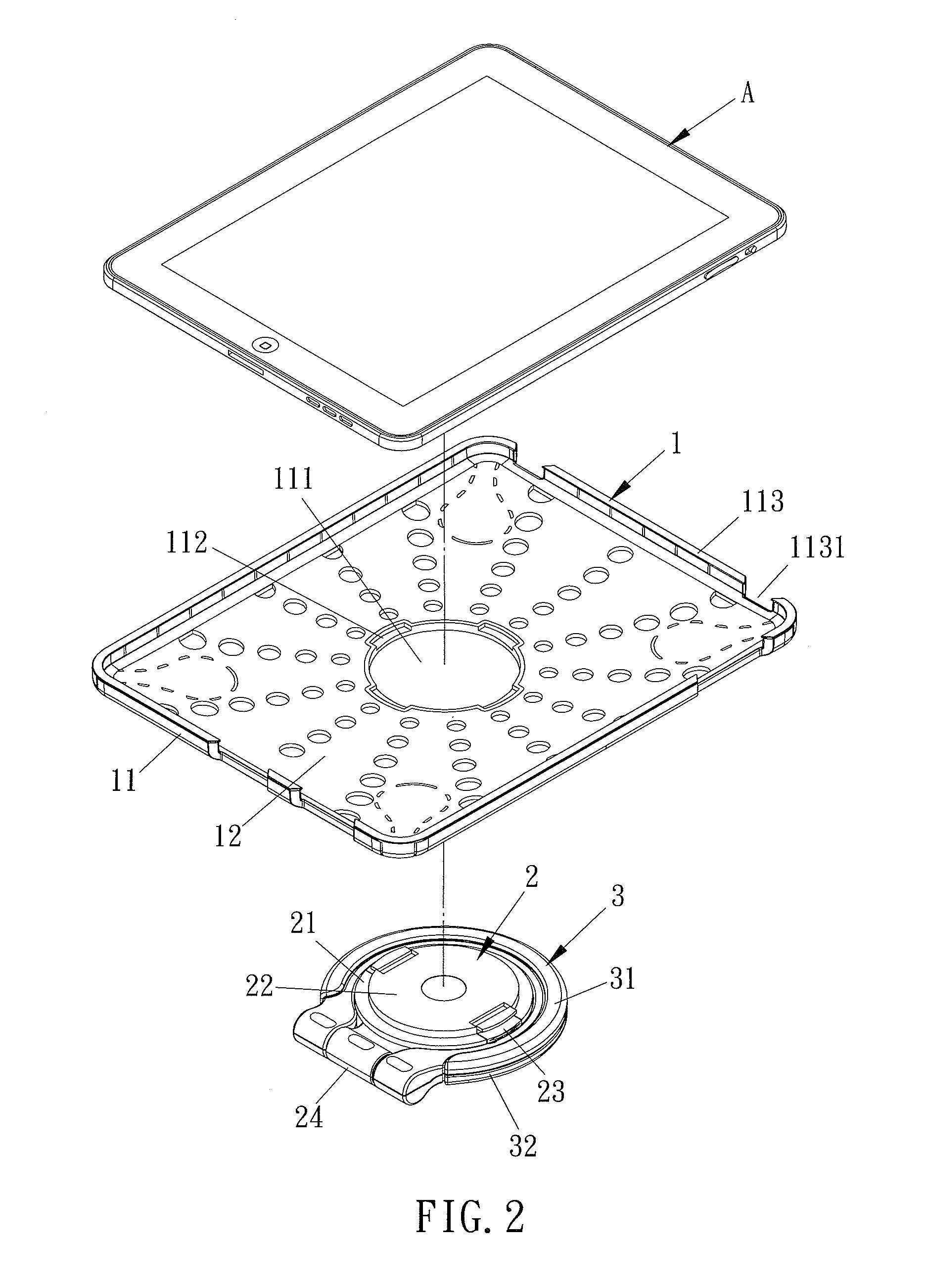
[0027]With reference to FIGS. 1-4, a support structure of a digital device according to the present invention comprises a holding unit 1, an angle adjusting mechanism 2, and a supporting unit 3, wherein the holding unit 1 is comprised of a tray member 11 and a soft protective pad 12 fitted therein to place the digital device A, the tray member 11 includes a circular hole 111 disposed on a central portion thereof, four retaining recesses 112 arranged around the hole 111 on a front end of the tray member 11 evenly, and a peripheral rib 113 formed around a peripheral side thereof, the peripheral rib 113 includes a plurality of notches 1131 formed thereon. As shown in FIGS. 6 and 7, the tray member 11 includes four through orifices 114 fixed at four corners thereof respectively, and each through orifice 114 is used to position an anti-slip cushion 121 extending from the protective pad 12; the angle adjusting mechanism 2 includes a seat 21, a circular tab 22 extending from a front end of...

second embodiment

[0032]With reference to FIG. 9, a support structure of a digital device according to the present invention comprises a holding unit 1 including a tray member 11, the tray member 11 includes a circular hole 111 disposed on a front end thereof, two opposite retaining recesses 112 arranged around the hole 111; a angle adjusting mechanism 2 comprised of a rotary disc 25, a coupling member 26, and a fixing member 27, the rotary disc 25 includes an annular projection 251 disposed on a front end thereof, and the projection 251 includes two opposite retainers 252 disposed on a peripheral side thereof to fit the projection 251 in the hole 111 of the tray member 11 of the holding unit 1 so that the retainers 252 are retained with the recesses 112 of the hole 111 of the tray member 11 of the holding unit 1 respectively; the rotary disc 25 includes an annular extension 253 form on a back end thereof, the extension 253 includes a number of arcuate cutouts 2531 arranged on an inner wall thereof e...

third embodiment

[0034]Referring to FIG. 12, a support structure of a digital device according to the present invention comprises an angle adjusting mechanism 2 including a bearing member 5 axially connected therewith, and the bearing member 5 includes a counter weight block 6 axially coupled therewith to support a holding unit 1 and the angle adjusting mechanism 2 on the desk fixedly.

[0035]Thereby, the support structure of the digital device of the present invention has the following advantages:

[0036]1. The holding unit 1 and the angle adjusting mechanism 2 are fixed in a retaining manner, accordingly the holding unit 1 is removed from the angle adjusting mechanism 2 easily to be portable conveniently, and the hole 111 of the tray member 11 of the holding unit 1 is grasped by the user's fingers to place the digital device A securely and safely, preventing the digital device A from sliding from the user's hand. Furthermore, the hole 111 is applicable for various digital devices A which are rotated h...


PUM


Abstract

A support structure of a digital device contains a holding unit including a tray member to place the digital device, the tray member including a circular hole disposed on a central portion thereof, a plurality of retaining recesses arranged around the hole on a front end of the tray member; an angle adjusting mechanism including a circular tab and a number of resilient locking devices attached around a peripheral side of the circular tab, such that the tab is fitted in the hole of the tray member of the holding unit so that the holding unit is rotated vertically or horizontally by using the angle adjusting mechanism; a supporting unit axially with the angle adjusting mechanism.

Description

BACKGROUND OF THE INVENTION[0001]1. Field of the Invention[0002]The present invention relates to supporting structure, and more particularly to a supporting structure of a digital device to place the digital device based on requirement.[0003]2. Description of the Prior Art[0004]A conventional digital device, such as a touch panel computer, a PDA, an electronic reader, is developed and used widely, and it is capable of being rotated horizontally or vertically to be portable and operated easily.[0005]However, such a conventional digital device is easy to fall from a user's hand to be broken, when the user touches its screen carelessly. Besides, the digital device has to be held by the user's hand, therefore the user will feel uncomfortable after operating it for a long period of time. When the digital device is put on a desk, the user can not view the screen clearly because of a reflected light from the screen, and it is inconvenient for the user to touch the screen. If the digital de...

Claims


Application Information

Patent Timeline
Patent Type & Authority Applications(United States)
IPC IPC(8): H05K7/14
CPCF16M11/041F16M11/105G06F1/1628F16M13/00F16M2200/024F16M11/2021
Inventor HO, CHI-PEIHO, CHI-DOU
Owner AIDMA ENTERPRISE
Why Eureka
Try Eureka