
Hanger for window drape and slide assembly including hanger

Inactive Publication Date: 2012-06-14
RUFFO FABIAN +1
View PDF11 Cites 15 Cited by
  • Summary
  • Abstract
  • Description
  • Claims
  • Application Information

AI Technical Summary

Benefits of technology

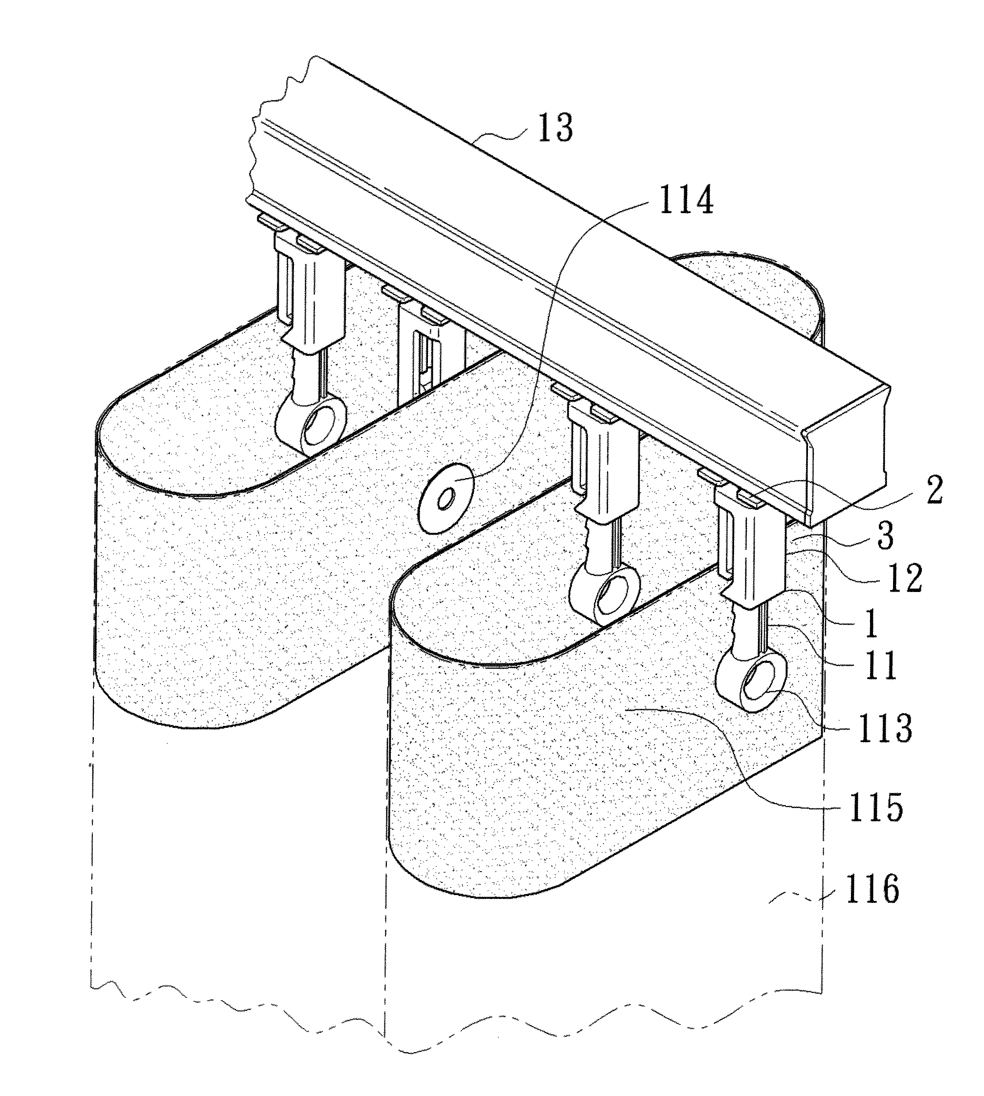
[0009]In use, a plurality of hangers is directly and slideably mounted to a track of a window drape. Alternatively, the hanger is mounted to a bottom of a slide to form a slide assembly, and a plurality of the slide assemblies is slideably mounted along the track of the window drape. The engaging portion on each hanger is coupled to one of a plurality of engagement portions of a snap tape that is fixed by sewing to a top edge of a drape of the window drape. A string is extended through the hangers to allow setting of the spacing between the hangers. The snap tape and the drape fixed to the snap tape are substantially S-shaped when viewed from top, providing creasing effect for the drape.
[0010]Since the hanger according to the present invention is adjustable, the spacing between the engaging portion and a bottom edge of the track can be changed according to the width of the snap tape. Thus, the hanger according to the present invention can be used with snap tapes of differing widths. Furthermore, the snap tape can be sewn to the top edge of the drape to provide stiffening effect for preventing drooping of the drape, preventing light beams from passing through the drooping portion of the drape, and avoiding weakening of the light-shielding effect of the drape. In a case that a wider snap tape is used to avoid drooping of the drape, the length-adjustable hanger according to the present invention allows use of the wider snap tape. Thus, drooping of the drape is avoided. Furthermore, use of the wider snap tape can provide stiffening effect such that the creasing of the drape can extend to the bottom of the drape, providing an aesthetically pleasing effect.
[0012]In use, a plurality of the slide assemblies is slideably mounted along the track of the window drape with the engaging portion on each slide assembly coupled to a drape of a window drape. The engaging portion on each slide assembly is coupled to one of a plurality of engagement portions of a snap tape that is fixed by sewing to a top edge of a drape of the window drape. A string is extended through the hangers to allow setting of the spacing between the slide assemblies. The snap tape and the drape fixed to the snap tape are substantially S-shaped when viewed from top, providing creasing effect for the drape.
[0013]Since the slide assembly according to the present invention is adjustable, the spacing between the engaging portion and a bottom edge of the track can be changed according to the width of the snap tape. Thus, the slide assembly according to the present invention can be used with snap tapes of differing widths. Furthermore, the snap tape can be sewn to the top edge of the drape to provide stiffening effect for preventing drooping of the drape, preventing light beams from passing through the drooping portion of the drape, and avoiding weakening of the light-shielding effect of the drape. In a case that a wider snap tape is used to avoid drooping of the drape, the length-adjustable slide assembly according to the present invention allows use of the wider snap tape. Thus, drooping of the drape is avoided. Furthermore, use of the wider snap tape can provide stiffening effect such that the creasing of the drape can extend to the bottom of the drape, providing an aesthetically pleasing effect.

Problems solved by technology

However, the length of the slide assembly is fixed and, thus, not adjustable according to differing needs.
Specifically, the vertical spacing between the ring and the bottom edge of the track is fixed, causing limitation to the width of the snap tape.
Namely, the slide assembly can not be used with snap tapes of differing widths.
In a case that a wider snap tape is required to avoid drooping of the drape, the conventional slide assembly can not be adjusted in length according to the width of the wider snap tape.
Furthermore, the length of the snap tape can not be increased such that it is impossible to use a wider snap tape to prevent drooping of the drape.
As a result, the creasing effect of the drape can not reach the bottom of the drape, failing to provide an aesthetically pleasing effect.

Method used


Image

  • Hanger for window drape and slide assembly including hanger
  • Hanger for window drape and slide assembly including hanger
  • Hanger for window drape and slide assembly including hanger

Examples


Embodiment Construction

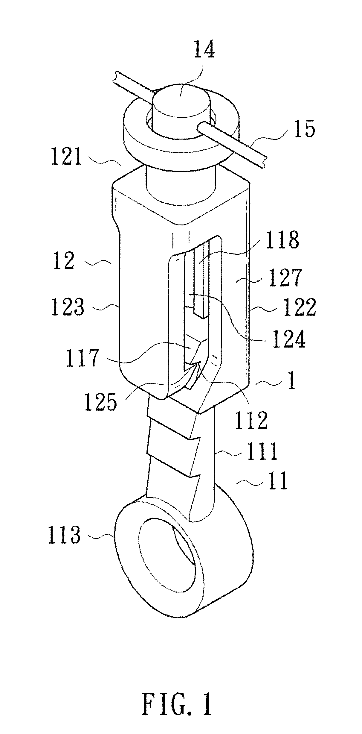
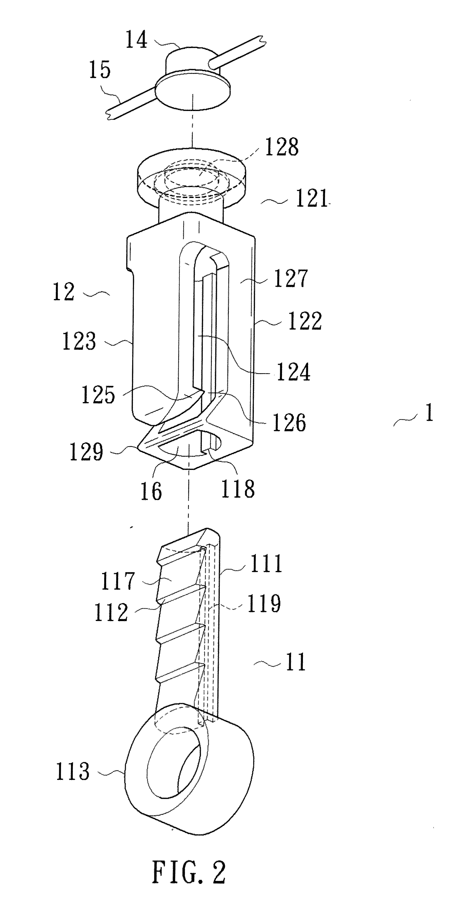
[0026]With reference to FIGS. 1-6, a hanger 1 according to the present invention includes an elongated member 11. The elongated member 11 includes a rod 111 and an engaging portion 113. The rod 111 includes a side having a plurality of positioning portions 112 spaced in a vertical direction. The engaging portion 113 is formed on a bottom of the rod 111. The engaging portion 113 is adapted to engage with an engagement portion 114. In the illustrated embodiment, the engaging portion 113 is in the form of a ring, and the engagement portion 114 is in the form of a button on a snap tape 115 that can be connected to a top edge of a drape 116 by such as sewing.

[0027]The hanger 1 further includes a coupling block 12 having a connecting head 121. The coupling block 12 further includes a body 122 and a resilient plate 123. The body 122 and the resilient plate 123 are located below the connecting head 121. The body 122 and the resilient plate 123 together define an elongated passageway 124 hav...


PUM


Abstract

A hanger includes an elongated member having a rod with a plurality of positioning portions spaced in a vertical direction. An engaging portion is formed on a bottom of the rod for engaging with an engagement portion. A coupling block includes a connecting head. The coupling block further includes a body and a resilient plate that are located below the connecting head. The body and the resilient plate together define a passageway having an opening in a lower end thereof. The rod is slideable in the passageway in the vertical direction. The resilient plate includes a free end having a hook that is spaced from the body. At least a portion of the hook extends into the passageway. The hook is releasably engaged with a selected one of the positioning portions. The resilient plate is operable to disengage the hook from the positioning portions.

Description

BACKGROUND OF THE INVENTION[0001]The present invention relates to a hanger for a window drape and a slide assembly including the hanger and, more particularly, to a length-adjustable hanger and a slide assembly including such a hanger.[0002]Window drapes are generally used in indoor decoration and provide several functions including preventing peeking, adjusting indoor brightness and temperature, insulating heat, blocking dust, and providing decoration.[0003]A wide variety of window drapes has been proposed to meet differing needs. Window drapes may include a plurality of slide assemblies for moving the drape. A type of slide assembly includes a slide having a sliding portion on each of two sides thereof for sliding along a track of a window drape. A hanger includes an engaging block engaged with an engaging groove in a bottom of the slide. A ring is provided at a bottom of the hanger and has a hole for engagement with one of a plurality of buttons on a snap tape that is fixed to a ...

Claims


Application Information

Patent Timeline
IPC IPC(8): A47H1/12A47H1/14A47H13/12
CPCA47H13/00A47H13/14Y10T16/353A47H15/02A47H13/16
Inventor RUFFO, FABIANKO, JAMES
Owner RUFFO FABIAN
Learn More