
Aseptic transfer port

a technology of transfer port and septic tank, which is applied in the direction of pipe heating/cooling, nuclear engineering, mechanical equipment, etc., can solve the problems of tumbling action of components, undesirable, if not prohibitive, and not allowing “dirty” particles to escape into

Inactive Publication Date: 2012-06-21
STTPHARMA
View PDF5 Cites 24 Cited by
  • Summary
  • Abstract
  • Description
  • Claims
  • Application Information

AI Technical Summary

Benefits of technology

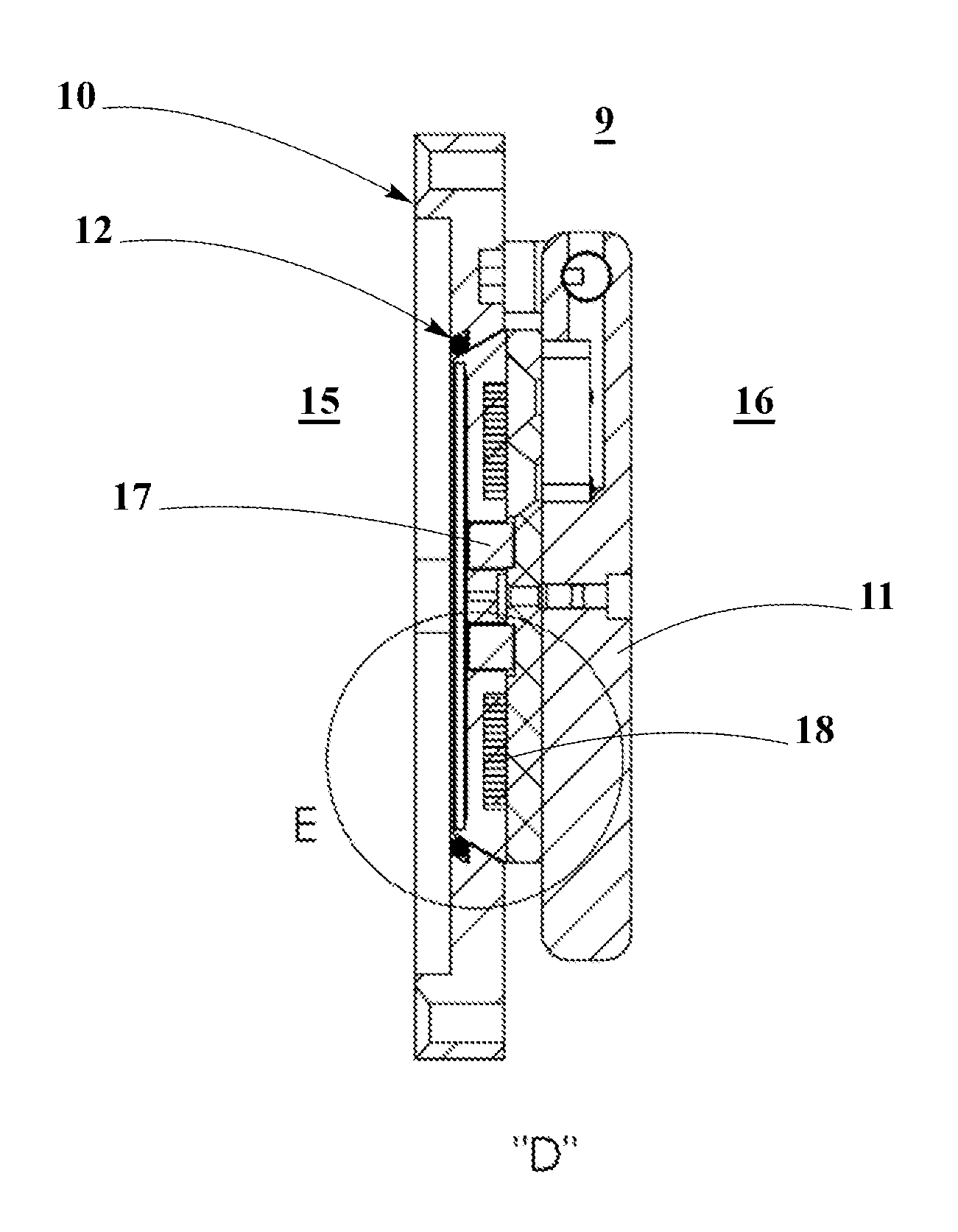
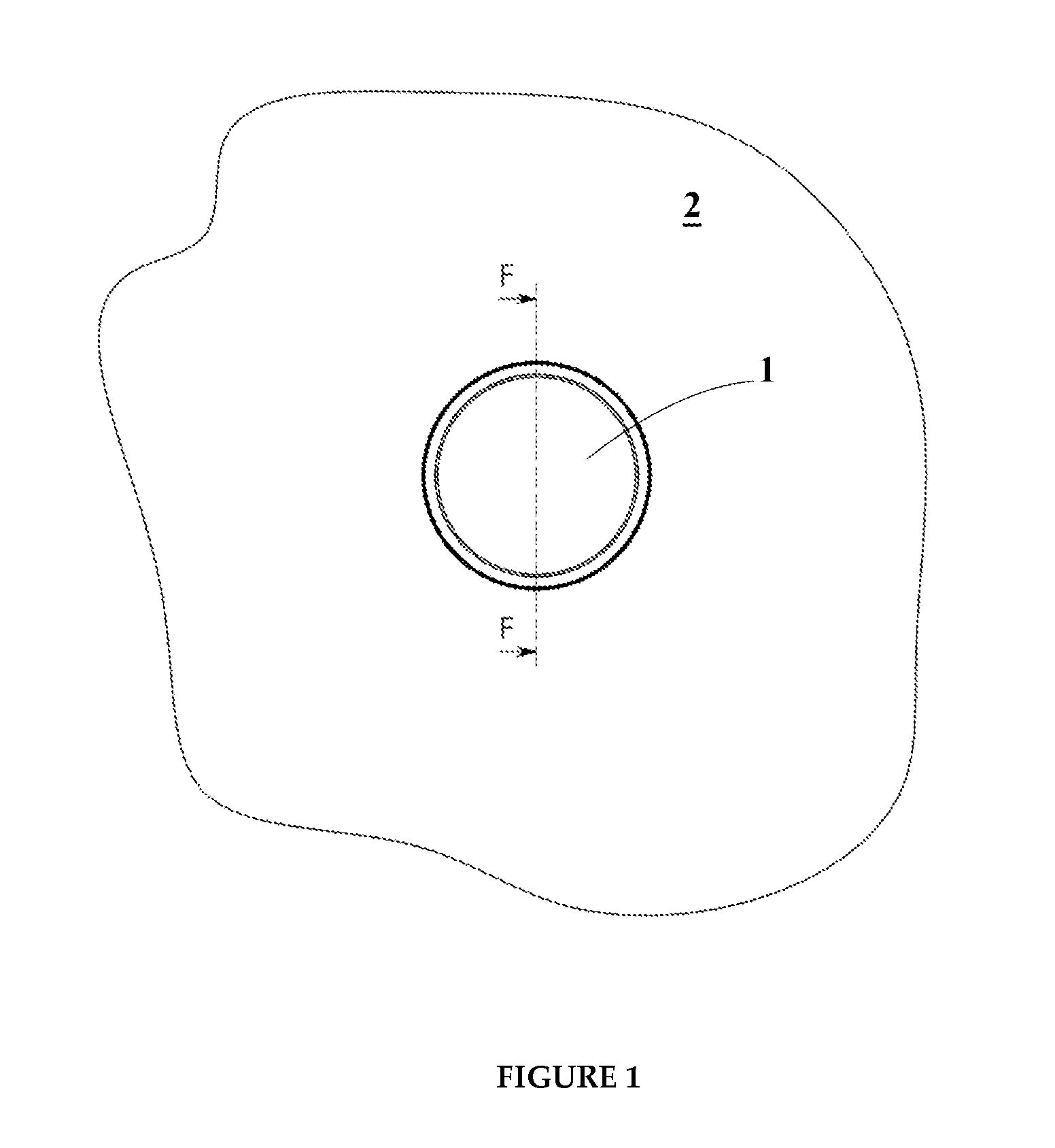
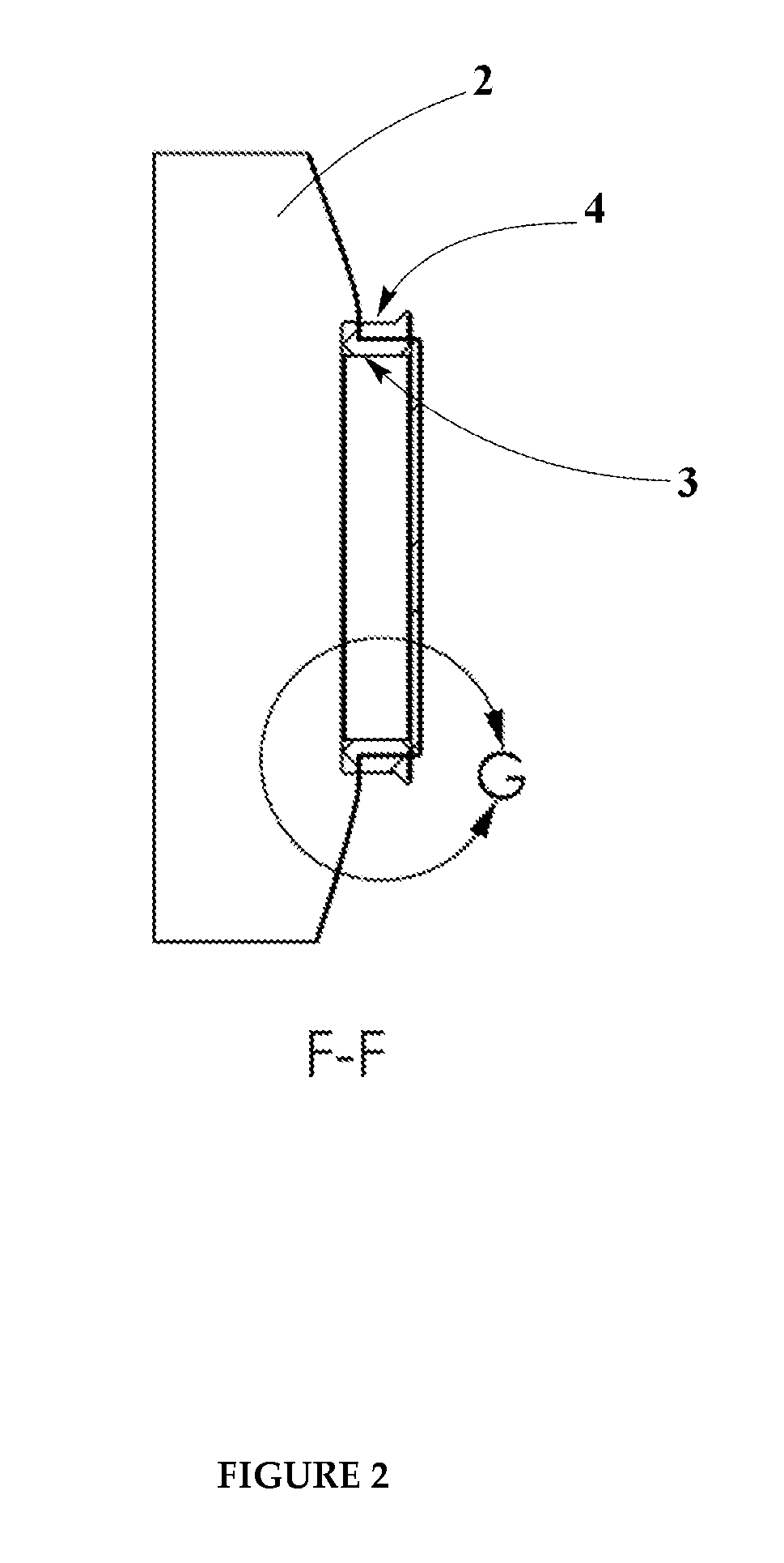
[0018]Embodiments of the present invention provide for a sealed system for aseptic transfer. Specifically, materials may be transferred through a transfer port in a barrier wall between a first environment and a second environment on opposite sides of the barrier wall, without contamination of the first environment. Such a system may include a film associated with the transfer port in the barrier wall and separating the first environment and the second environment, a sealed transfer container having at least one portion comprised of the film, and means for creating a hole in the film upon connection of the sealed transfer container to the transfer port.
[0019]Additional embodiment may additionally include a first ring of variable width and depth internal to the container of the second environment having a perimeter in close contact with an internal surface of the film of the transfer container, the ring comprising a flange extruding from a perimeter furthest from the internal surface of the flexible film, a second ring comprised of material reactive to the means for thermally creating the hole in the film, the second ring seated within the perimeter of the first ring and when subjected to the hole creation means, acting as a cutting surface of the film located within the perimeter of the first ring, a plug of material of width equal to a width of the first ring which acts as the door of a Beta port, a third ring comprising a flange and having a diameter such that the third ring fits tightly over the perimeter of the first ring on an external surface of the transfer container, a fourth ring having a flange and an inside and outside perimeter extending through the transfer port in the barrier wall separating the first and second environments, wherein the transfer port has an inner periphery, and the outside perimeter of the fourth ring being in leak-proof sealed engagement with the periphery of the transfer port and having a first passage through the ring, a hinged door on the one side of the barrier wall moveable from a first closed position in the first passage in leak-proof sealed engagement with the inside perimeter of the first ring to a second open position free of the first passage through the first ring; and a complementary locking means on the first and second rings for rigidly securing the rings together in leak-proof sealed engagement.

Problems solved by technology

In recent years, because of the expense and operational difficulties of maintaining so-called “clean rooms” into which operators enter to carry out procedures, the use of isolation barriers has become common practice in various industries (e.g., pharmaceuticals).
To prevent contamination of the “clean” environment, the docking process places the “dirty” surfaces of the RTP and of the transfer container in sealed contact with each other, thus not permitting “dirty” particles to escape into the “clean” environment.
The rotation necessary to dock the transfer container onto an RTP may cause tumbling action of the components which are contained within the transfer container.
This tumbling action may be acceptable when transferring soft plastic components such as stoppers or cleaning supplies, but it is undesirable, if not prohibitive, when transferring heavy or delicate machine components.
In addition, the rotation of the container upon docking does not permit interface of the container to a lifting device such as a hoist or crane.
There is also a problem with the so called “ring of concern.” Prior to docking, the face of the canister and the outside of the isolator port are exposed to the environment and are potentially contaminated.
If, however, the container remains stored long enough, this pressurization can be compromised.
A problem occurs, however, with respect to keeping the environment clean when it is confronted with the container that has been stored under unclean conditions.
The procedure for sterilizing the port, however, is time-consuming and difficult to handle.
There is also a risk that an un-sterilized port may be inserted into the clean room by mistake, since there is no way to immediately determine whether the port is clean or not.

Method used


Image

  • Aseptic transfer port
  • Aseptic transfer port
  • Aseptic transfer port

Examples


Embodiment Construction

[0035]A novel concept for an aseptic transfer port is disclosed. Embodiments of the present invention provide for joining and sealing together two isolated enclosures that can be cooperatively joined and opened without introducing contaminants from the environment external to the two enclosures. At least part of each enclosures may be made from a film where a hole can be created upon attachment, thereby effecting an opening. While a typical film may be made of a flexible plastic, other materials with different degrees of flexibility / rigidity are possible. A preferred embodiment involves inductively heating a metal component (e.g., plate or ring), thereby thermally cutting a hole through a plastic film. Some embodiments may optionally further include added inductively heated metal components that can effect microbial sterilization in and around the sealing area between the enclosures.

[0036]Other materials known in the art for providing a barrier impermeable to contaminants may also b...


PUM


Abstract

Rapid transfer port (RTP) systems for transferring articles between two environments (e.g., an isolator barrier system and a transfer container) are provided. Such systems may be adapted to be mated to one another by a docking operation. More particularly, such systems may provide a container assembly for use with an RTP of the type that does not require the transfer container port (beta port) which mates, for example, with the isolator barrier system port (alpha port) to breach the integrity of the container until attachment to the isolator barrier system port (alpha port 9). The container assembly may have an enclosure that, during docking, is not required to be exposed to the clean environment such as an isolator barrier system.

Description

CROSS-REFERENCE TO RELATED APPLICATIONS[0001]The present patent applications claims the priority benefit of U.S. provisional patent application No. 61 / 425,211 filed on Dec. 20, 2010, the disclosure of which is incorporated by reference herein.BACKGROUND OF THE INVENTION[0002]1. Field of the Invention[0003]The invention generally relates to rapid transfer port (RTP) systems for transferring articles between two environments (such as an isolator barrier system and a transfer container) that are adapted to be mated to one another by a docking operation. More particularly, the present invention may relate to a container assembly for use with an RTP of the type that does not require that the integrity of the transfer container port (e.g., a beta port) be breached until attachment with an isolator barrier system (e.g., an alpha port). The container assembly may have an enclosure that, during docking, is not required to be exposed to the clean environment such as an isolator barrier system...

Claims


Application Information

Patent Timeline
IPC IPC(8): F16L53/00F16L19/00
CPCA61L2/26A61L2202/123B01L1/02G21F5/00G21F7/005G21F7/047
Inventor YOUNG, THOMAS MITCHEL
Owner STTPHARMA
Learn More