
Television Cabinet

Inactive Publication Date: 2012-06-21
ER WONEN
View PDF19 Cites 12 Cited by
  • Summary
  • Abstract
  • Description
  • Claims
  • Application Information

AI Technical Summary

Benefits of technology

[0016]In the embodiment as described in claim 2, the holder is slidably connected with the bracket and thus the holder, during moving to the operating position, can move upwards along the bracket by means of the pulling cable. Through this a higher position of the holder above the horizontal panel is obtained, without requiring additional space in the storage position under the horizontal panel.
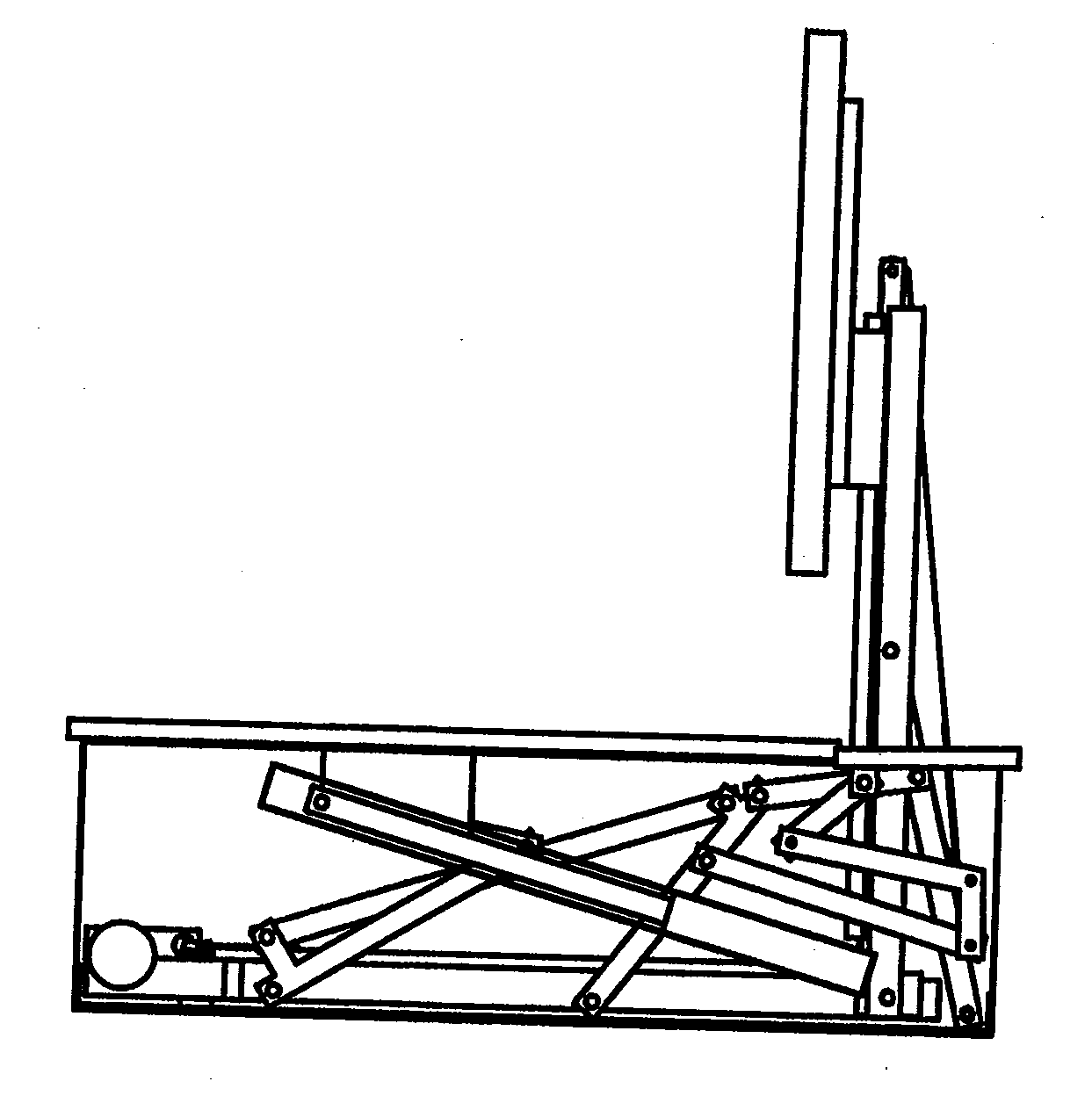
[0018]A special advantage of the cabinet according to the invention is that during movement of the holder (during use with the television device attached) from the storage position to the operating position and back again, only the horizontal panel, respectively a part thereof, moves outside the vertical contours of the cabinet. However, it is easily arranged that this is not posing any problems. The holder (during use with the television device attached) itself remains completely inside the vertical contours of the cabinet.
[0021]When the horizontal panel, respectively a major part thereof, remains horizontal during the movement, pieces that have been placed thereon can remain in their position during this movement. In the case of the embodiment, for example where the cabinet functions as a coffee table, drinks could be located on the table, such cups of coffee, tea or glasses with other drinks. In that case it is advantageous that the cabinet according to the invention is arranged in such a way that during the movement there is no or a very limited possibility that some of the drinks are spilled over the table. Therefore it is in a preferred embodiment of the invention that the drive comprises a control such that the part of the horizontal panel that keeps its horizontal position during movement is controlled in such a way that this undergoes only limited acceleration that does not exceed a predefined threshold value. In such a way a preferred embodiment of the invention can be arranged so that the movement is very smooth and all matters that are positioned on top of the horizontal panel can keep their position.

Problems solved by technology

A switched off television screen usually does not provide a pleasant sight.
The known television cabinets have the disadvantage that they are arranged for accommodating a television device.

Method used


Image

  • Television Cabinet
  • Television Cabinet
  • Television Cabinet

Examples


Embodiment Construction

[0030]In a preferred embodiment of the cabinet according to the invention the drive can be operated by remote control, so that using a remote control device the user can switch from storage position to operating position and from operating position to storage position.

[0031]First, it is noted that not all figures comprise all reference numbers. For each series of figures only reference numbers are indicated thereon where they are most clear for understanding the operation of the embodiment of the invention shown.

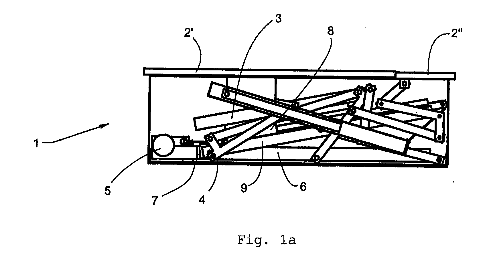
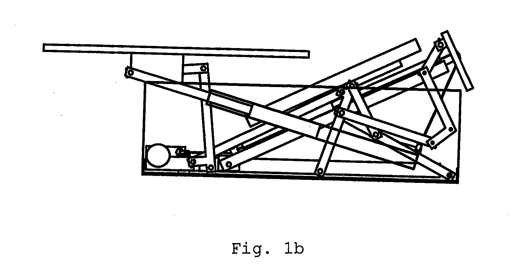
[0032]The overall operation will be described with reference to FIGS. 1a-e.

[0033]FIG. 1a shows a cabinet 1 with a horizontal panel 2 that is divided in two parts, 2′ and 2″, in which below the horizontal panel 2′, 2″ a display screen, visual monitor or television device 3 is situated in the storage position. The horizontal panel in this embodiment is divided into two parts, being a part 2′, which comprises the largest part of the horizontal panel, and a part 2″ that forms t...


PUM


Abstract

A cabinet comprising a holder for attachment of a device comprising a display screen, such as a television device, wherein the cabinet at least comprises a horizontal panel. The cabinet comprises an arrangement for moving the display screen device between two positions, wherein in a first position, called storage position, the display screen is stored below the horizontal panel with the display screen in a lying position and in a second position, called operating position, the display screen is situated externally of the cabinet above the horizontal panel with the screen in standing, essentially vertical position.

Description

CROSS-REFERENCE TO RELATED APPLICATIONS[0001]This application is a continuation application of Netherlands Patent Application Serial No. 2005867, entitled “Television Cabinet”, filed on Dec. 16, 2010, and the specification and claims thereof are incorporated herein by reference.STATEMENT REGARDING FEDERALLY SPONSORED RESEARCH OR DEVELOPMENT[0002]Not Applicable.INCORPORATION BY REFERENCE OF MATERIAL SUBMITTED ON A COMPACT DISC[0003]Not Applicable.COPYRIGHTED MATERIAL[0004]Not Applicable.BACKGROUND OF THE INVENTION[0005]1. Field of the Invention (Technical Field)[0006]The present invention relates to a cabinet comprising a holder for attachment to the holder of a device comprising a display screen, such as a television device or a computer monitor. In cases where a television device is mentioned hereafter a device comprising a display screen is meant and also other devices with a display screen other than a television device, such as a computer monitor are considered to be included.[0...

Claims


Application Information

Patent Timeline
IPC IPC(8): H05K5/02
CPCA47B81/061A47B21/0073
Inventor ROZESTRATEN, REINIER I. J.
Owner ER WONEN
Learn More