Interventionless set packer and setting method for same

a technology of set packer and set packer, which is applied in the direction of sealing/packing, fluid removal, borehole/well accessories, etc., can solve the problems of negative impact on the economics of the project, add unacceptable complications and risks, and the bottom-up hydrostatic setting module may not be ideal for applications

Active Publication Date: 2012-06-28
HALLIBURTON ENERGY SERVICES INC
View PDF5 Cites 30 Cited by
  • Summary
  • Abstract
  • Description
  • Claims
  • Application Information

AI Technical Summary

Benefits of technology

[0014]In another aspect, the present invention is directed to a method for setting a packer in a wellbore. The method includes providing a packer having a packer mandrel with a seal assembly, a slip assembly and a piston slidably disposed thereabout; running the packer into the wellbore; resisting a force acting on the piston that generated by a pressure difference between pressure in the wellbore and pressure in a chamber defined between the piston and the packer mandrel by restraining movement of the piston toward the seal assembly with a release assembly; actuating the release assembly with a profile in the wellbore; and responsive to the pressure difference, longitudinally shifting the piston relative to the packer mandrel toward the seal assembly, to operate the seal assembly from a running position to a radially expanded sealing position and to operate the slip assembly from the running position to the radially expanded gripping position, thereby setting the packer.
[0015]In a further aspect, the present invention is directed to a packer for use in a wellbore. The packer includes a packer mandrel with a seal assembly slidably disposed thereabout. A piston is slidably disposed about the packer mandrel and defines a chamber therewith. A release assembly is disposed about the packer mandrel and is releasably coupled to the piston. The release assembly initially restrains movement of the piston toward the seal assembly resisting a force generated by a pressure difference between pressure in the wellbore and pressure in the chamber until actuation of the release assembly allows the pressure difference to shift the piston longitudinally relative to the packer mandrel toward the seal assembly to operate the seal assembly from a running position to a radially expanded sealing position, thereby setting the packer.
[0016]In one embodiment, the release assembly may include a collect assembly that is disposed about the packer mandrel. In another embodiment, the release assembly may include a split ring disposed about the packer mandrel and at least on release key positioned at least partially between the split ring and the piston. In a further embodiment, the release assembly may include a collect assembly disposed about the packer mandrel, a sleeve slidably disposed about the packer mandrel and a frangible member coupling the piston and the packer mandrel. With any of these embodiments, the packer may include a time delay assembly disposed about the packer mandrel that is operable to prevent premature actuation of the release assembly.
[0017]In yet another aspect, the present invention is directed to a packer for use in a wellbore. The packer includes a packer mandrel with a seal assembly and a slip assembly slidably disposed thereabout. A piston is slidably disposed about the packer mandrel and defines a chamber therewith. A release assembly is disposed about the packer mandrel and is releasably coupled to the piston. The release assembly initially restrains movement of the piston toward the seal assembly and the slip assembly resisting a force generated by a pressure difference between pressure in the wellbore and pressure in the chamber until actuation of the release assembly allows the pressure difference to shift the piston longitudinally relative to the packer mandrel toward the seal assembly and the slip assembly to operate the seal assembly from a running position to a radially expanded sealing position and to operate the slip assembly from a running position to a radially expanded gripping position, thereby setting the packer.

Problems solved by technology

As operators increasingly pursue production completions in deeper water offshore wells, highly deviated wells and extended reach wells, the rig time required to set a tubing plug and thereafter retrieve the plug can negatively impact the economics of the project, as well as add unacceptable complications and risks.
However, the bottom-up hydrostatic setting module may not be ideal for applications where the wellbore annulus and production tubing cannot be pressured up simultaneously.
The production tubing cannot be pressured up in either of these applications because the tubing extends as one continuous conduit out to the pay zone where no pressure, or limited pressure, can be applied.
However, when the packer sealing elements start to engage the casing, the limited annular area between the packer and the lower sealing device becomes closed off and can no longer communicate with the upper annular area that is being pressurized from the surface.
Thus, the trapped pressure in the limited annular area between the packer and the lower sealing device is soon dissipated and may or may not fully set the packer.

Method used


Image

  • Interventionless set packer and setting method for same
  • Interventionless set packer and setting method for same
  • Interventionless set packer and setting method for same

Examples


Embodiment Construction

[0032]While the making and using of various embodiments of the present invention are discussed in detail below, it should be appreciated that the present invention provides many applicable inventive concepts which can be embodied in a wide variety of specific contexts. The specific embodiments discussed herein are merely illustrative of specific ways to make and use the invention, and do not delimit the scope of the present invention.

[0033]In the following description of the representative embodiments of the invention, directional terms, such as “above”, “below”, “upper”, “lower”, etc., are used for convenience in referring to the accompanying drawings. In general, “above”, “upper”, “upward” and similar terms refer to a direction toward the earth's surface along a wellbore, and “below”, “lower”, “downward” and similar terms refer to a direction away from the earth's surface along the wellbore.

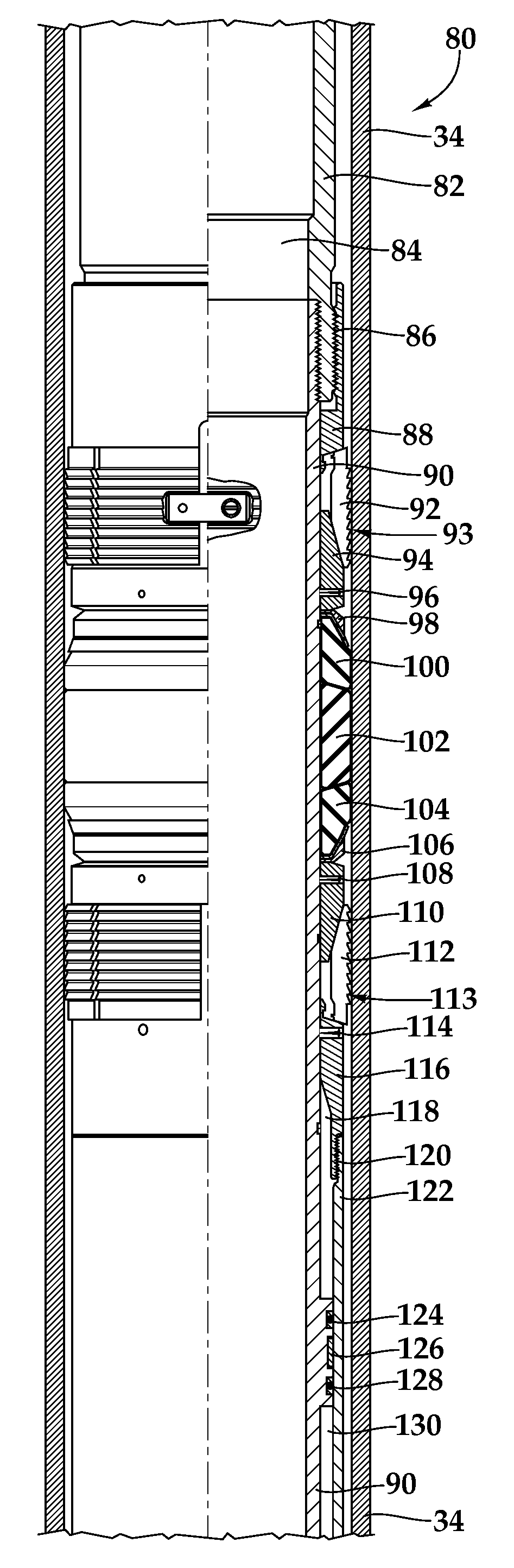
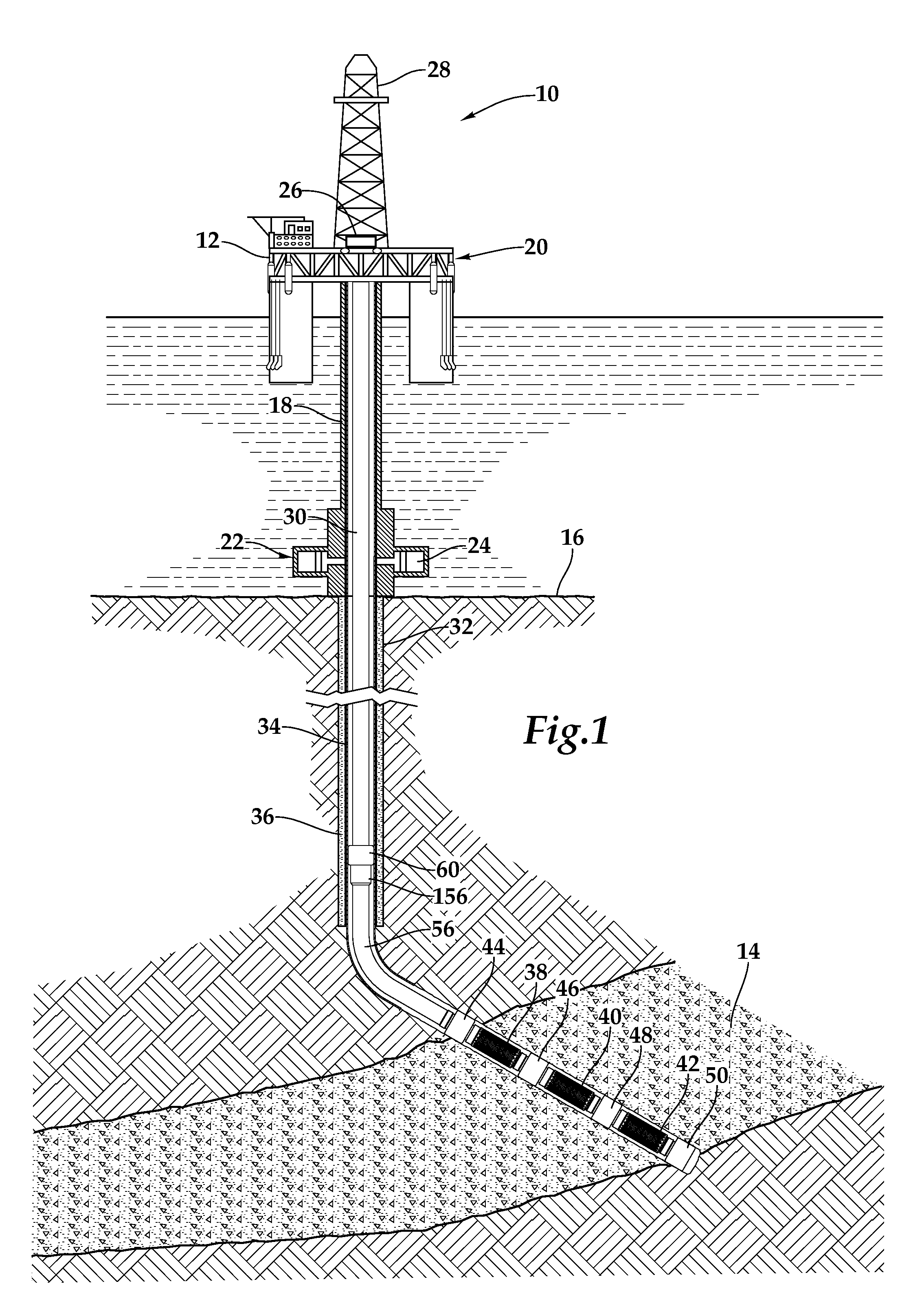
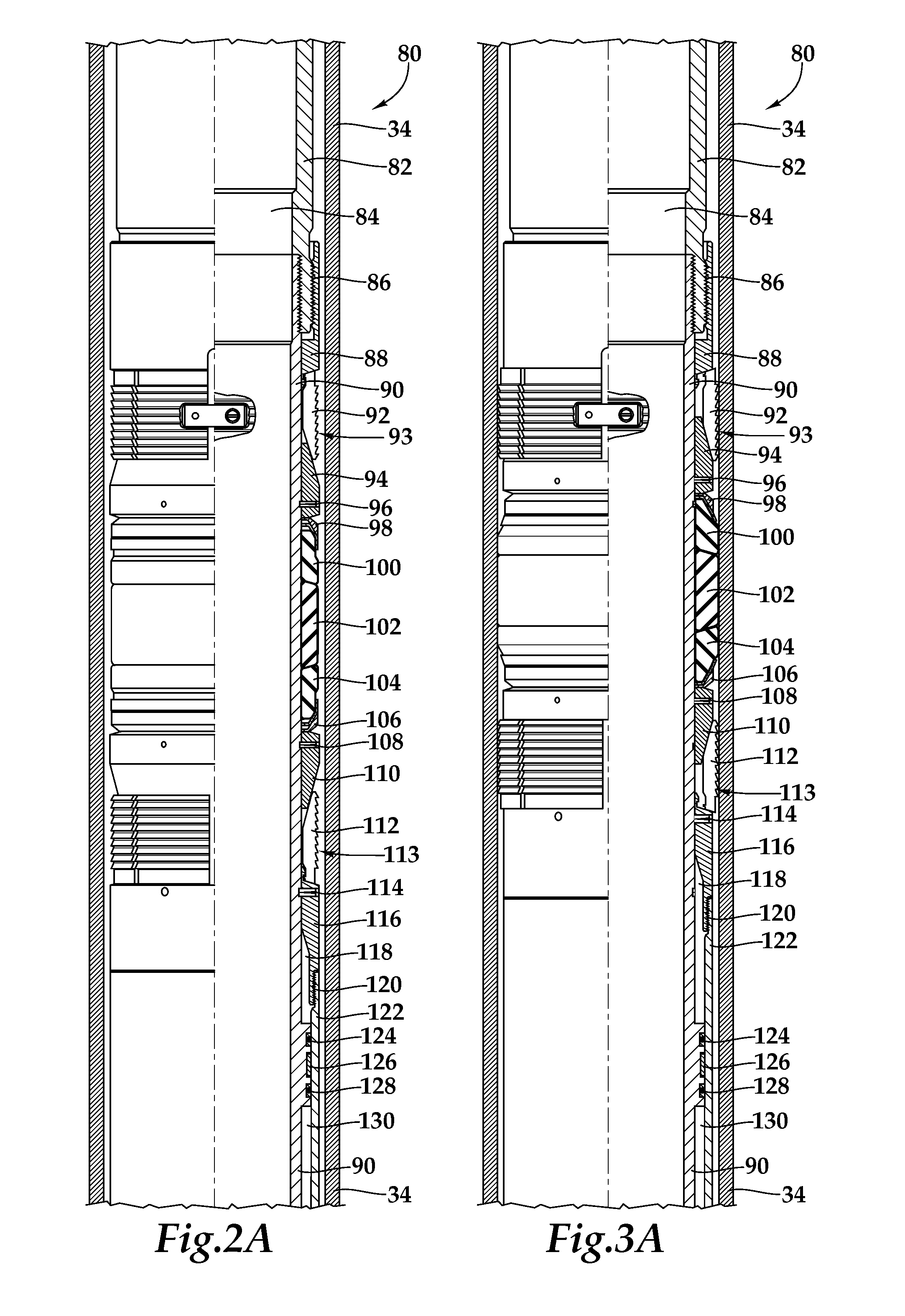
[0034]Referring initially to FIG. 1, several interventionless set packers in a completion s...


PUM


Abstract

A packer (80) for establishing sealing engagement with a surface disposed in a wellbore includes a packer mandrel (90) and a seal assembly (100, 102, 104) slidably disposed about the packer mandrel (90). The seal assembly (100, 102, 104) has a running position and a radially expanded sealing position. A piston (122) is slidably disposed about the packer mandrel (90) and operably associated with the seal assembly (100, 102, 104). A release assembly 145 is disposed about the packer mandrel (90) and is releasably coupled to the piston (122) such that actuation of the release assembly (145) decouples the release assembly (145) from the piston (122) allowing the piston (122) to shift longitudinally relative to the packer mandrel (90) to operate the seal assembly (100, 102, 104) from the running position to the radially expanded sealing position, thereby setting the packer (80).

Description

CROSS-REFERENCE TO RELATED APPLICATIONS[0001]The present application is a continuation in part of co-pending application Ser. No. 12 / 174,793, filed Jul. 17, 2008, now U.S. Pat. No. 7,967,077 issued Jun. 28, 2011, the entire disclosure of which is incorporated herein by this reference.TECHNICAL FIELD OF THE INVENTION[0002]This invention relates, in general, to packer setting mechanisms used in a wellbore that traverses a subterranean hydrocarbon bearing formation and, in particular, to an interventionless set packer and method for setting same.BACKGROUND OF THE INVENTION[0003]Without limiting the scope of the present invention, its background will be described in relation to setting packers, as an example.[0004]In the course of treating and preparing a subterranean well for production, well packers are commonly run into the well on a conveyance such as a work string or production tubing. The purpose of the packer is to support production tubing and other completion equipment, such as...

Claims


Application Information

Patent Timeline
Patent Type & Authority Applications(United States)
IPC IPC(8): E21B33/128E21B23/06E21B33/12
CPCE21B33/1285E21B33/1295H04N21/435H04N21/478H04N21/488
Inventor MCGLOTHEN, JODY RAYEZELL, MICHAEL D.FALCONER, RODERICK BRANDSCOTT, JAMES W.
Owner HALLIBURTON ENERGY SERVICES INC
Why Eureka
Try Eureka