
Blade holder with adjusting slide

Inactive Publication Date: 2019-02-07
DIENES WERKE FUER MASCHTEILE
View PDF33 Cites 1 Cited by
  • Summary
  • Abstract
  • Description
  • Claims
  • Application Information

AI Technical Summary

Benefits of technology

The present invention provides a blade holder with a locking mechanism that prevents the holder from being actuated when the adjusting slide is moved out of its starting position. This ensures that the lower blade is not damaged during the adjusting process and that the blade holder can be used for a cutting process only when the adjusting slide is moved back again into its starting position. The locking takes place electrically or electronically, preventing an indirect actuation of the blade holder actuator. The actuation of the entire longitudinal cutting machine is prevented when the adjusting slide of an individual blade holder is moved out from its starting position.

Problems solved by technology

If the blade head of the positioned blade holder is lowered automatically for the cutting process, it was proven that the adjusting slide, which is not moved back inadvertently into its starting position, can negatively effect the cutting process.

Method used


Image

  • Blade holder with adjusting slide
  • Blade holder with adjusting slide
  • Blade holder with adjusting slide

Examples


Embodiment Construction

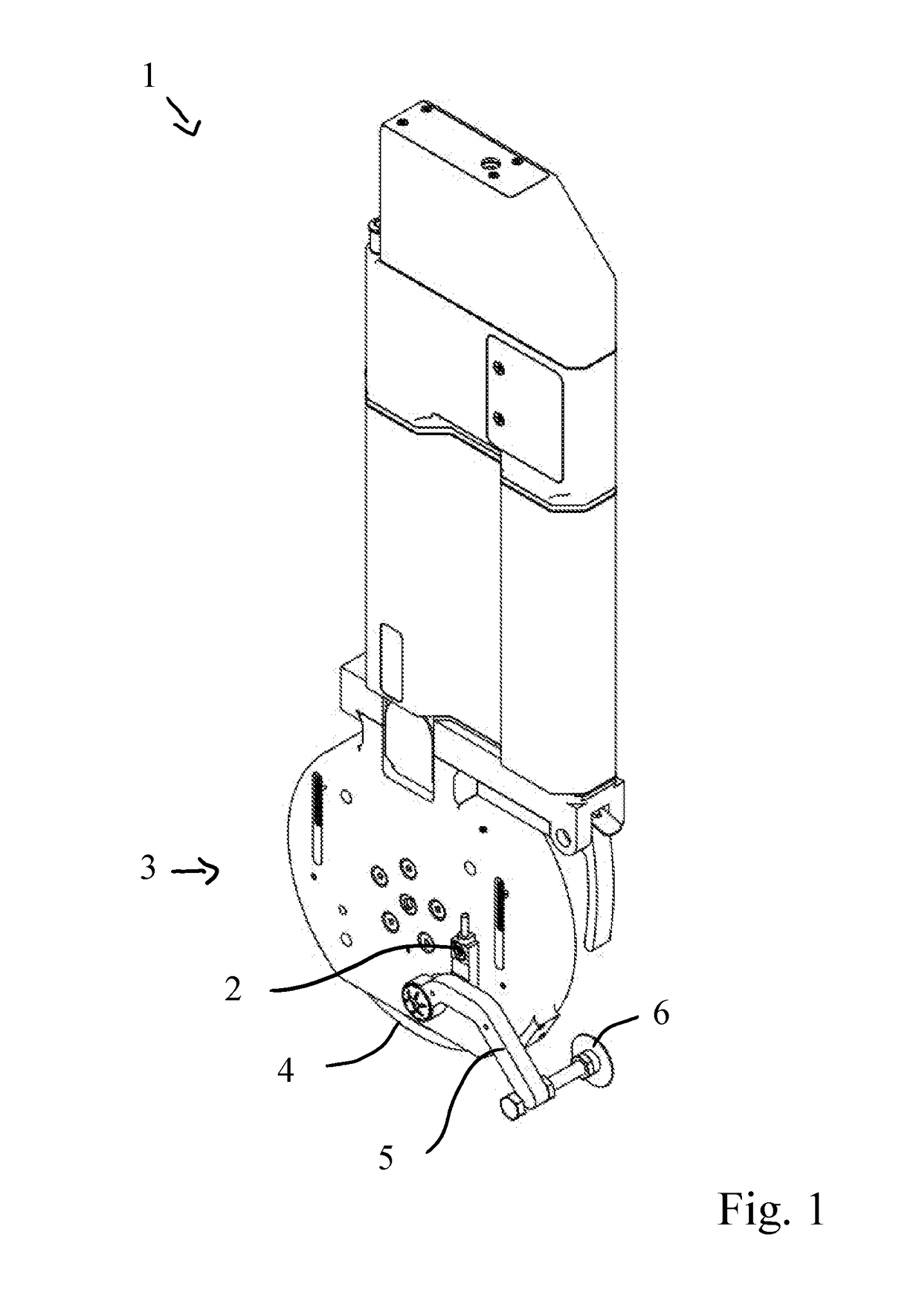
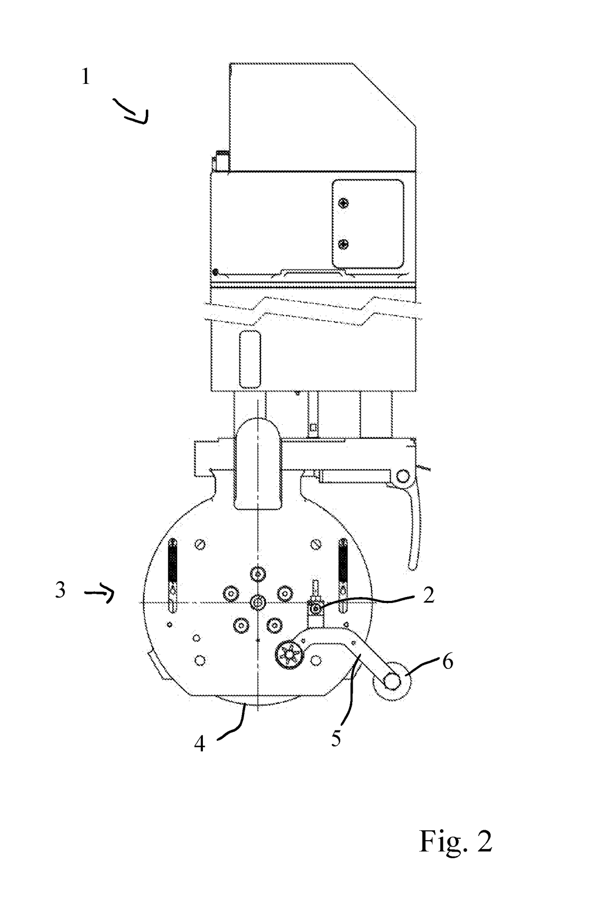
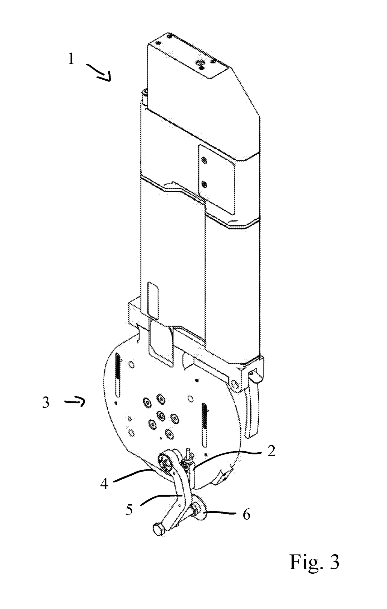
[0027]The blade holder 1 shown in the figures includes a locking device (not shown), with which the blade holder 1 is displaceable along a traverse (not shown) of a longitudinal cutting machine and which can be fixed to this traverse.

[0028]The blade holder 1 also includes a blade head 3, to which a circular blade 4 is attached. The blade head can be lowered by means of an actuator.

[0029]The blade holder 1 also includes an adjusting slide 5 for positioning the blade holder 1 on the traverse. In this connection, the adjusting slide 5 has a contact element 6, whose relative vertical position corresponds with the position of the cutting edge of the circular blade 4. The starting position of the adjusting slide 5 is shown in FIGS. 1 and 2.

[0030]For positioning of the blade holder 1 on the traverse, the adjusting slide 5 is pivoted downward, so that the contact element 6 can be brought into contact with a cutting edge of a lower blade (not shown) (see FIGS. 3 and 4). As soon as the blade ...


PUM

PropertyMeasurementUnit
Energyaaaaaaaaaa

Abstract

A blade holder (1) for a longitudinal cutting machine includes a rotatably mounted blade head (3) for holding a circular blade (4) and at least one locking device (2). At least one actuator actuates an element of the blade holder (1), and a moveably mounted adjusting slide (5) positions the blade head (3) on the longitudinal cutting machine. The adjusting slide (5) for positioning of the blade head (3) is moveable from a starting position to a positioning point. With the blade holder, materials can be cut perfectly with high precision. In particular, materials such as tissue, non-woven materials, paper, OLED film, displays, battery film, lithium batteries, aluminum, copper film, anodes, and cathodes can be cut.

Description

CROSS-REFERENCE TO RELATED APPLICATION[0001]This application claims the priority date of Aug. 2, 2017, the filing date of the German patent application DE 10 2017 117 524.5.BACKGROUND OF THE INVENTION[0002]The present invention relates to a blade holder for a longitudinal cutting machine, with a rotatably mounted blade head for holding a circular blade, with at least one hold-open device, in particular, for fixing the blade holder to a traverse of the longitudinal cutting machine, with at least one actuator for actuation of an element of the blade holder, and with a moveably mounted adjusting slide for, in particular, manual positioning of the blade head relative to the longitudinal cutting machine, whereby the adjusting slide is moveable for positioning of the blade head from a starting position into a positioning point.[0003]Applicant intends that the phrase “easy set” refers to blade holders with the above-described features. For example, Applicant refers to the blade holder with...

Claims


Application Information

Patent Timeline
IPC IPC(8): B23D45/02
CPCB23D45/021B26D1/151B26D1/141B26D7/2635B26D1/14
Inventor SUPE-DIENES, RUDOLF
Owner DIENES WERKE FUER MASCHTEILE
Learn More