
Bearing lubricator, controller and associated method

a technology of bearing lubricator and controller, which is applied in the direction of mechanical equipment, rotary machine parts, transportation and packaging, etc., can solve the problems of difficult optimization of the frequency of greasing and the amount to apply to each bearing, the insufficient optimization of the bearing life, and the high cost of the process

Active Publication Date: 2019-04-25
REGAL BELOIT AMERICA
View PDF0 Cites 1 Cited by
  • Summary
  • Abstract
  • Description
  • Claims
  • Application Information

AI Technical Summary

Benefits of technology

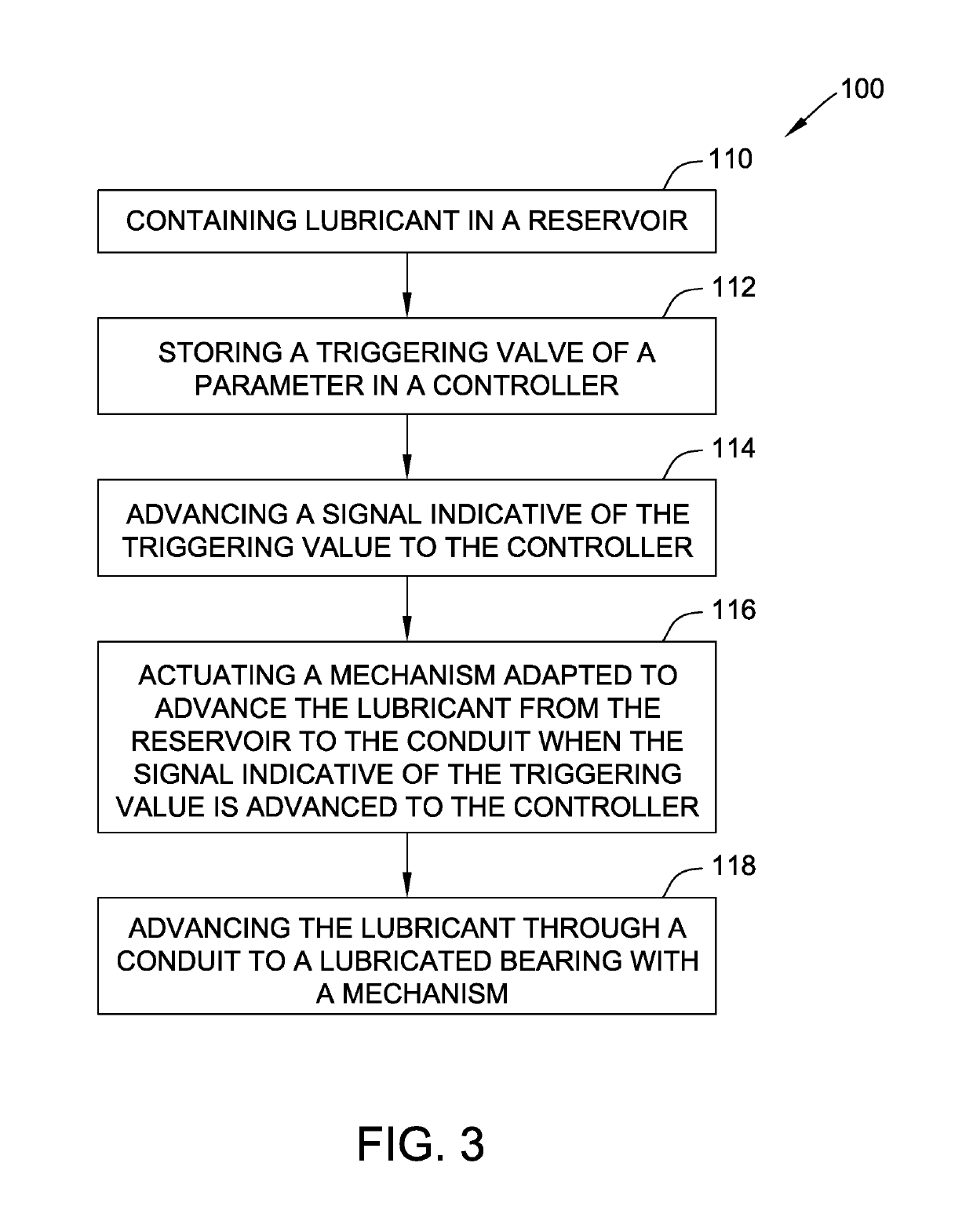
The invention is a bearing lubricator that is designed to lubricate a lubricated bearing. The lubricator includes a reservoir, a conduit, and a mechanism that is connected to the reservoir and conduit. The mechanism is designed to move the lubricant from the reservoir to the conduit when activated. The lubricator also includes a sensor that measures a parameter of the bearing and sends a signal to a controller. The controller stores a triggering value of a parameter and is adapted to actuate the mechanism when the triggering value is advanced. The lubricator can be programmed to lubricate multiple bearings and can communicate with remote devices and the cloud. The technical effects of the invention include improved lubrication of bearings, reduced downtime for maintenance, and improved efficiency of lubricant usage.

Problems solved by technology

Such a process is expensive and, because of this expense, may not be done sufficiently to optimize bearing life.
In addition, the frequency of greasing and the amount to apply to each bearing is hard to optimize due to widely varying conditions in the application of the bearings.
While attempts have been made to provide systems that automate, at least partially, the delivery of lubricant to bearings, these systems are expensive to purchase and to install, hard to financially justify, and difficult to maintain.
These systems require sensors at each bearing so that the proper amount of lubricant is applied to each bearing further adding to the cost of these systems.

Method used


Image

  • Bearing lubricator, controller and associated method
  • Bearing lubricator, controller and associated method
  • Bearing lubricator, controller and associated method

Examples


Embodiment Construction

[0066]The method, systems and apparatus described herein facilitate the lubrication a bearing.

[0067]The methods, systems, and apparatus described herein assist in lubrication bearings. The methods, systems, and apparatus described herein may also facilitate the monitoring of condition of bearings in a device. Furthermore, the methods, systems, and apparatus described herein provide for reduced maintenance cost and improved reliability of a device.

[0068]Technical effects of the methods, systems, and apparatus described herein include improved performance and / or quality and / or reduced labor costs.

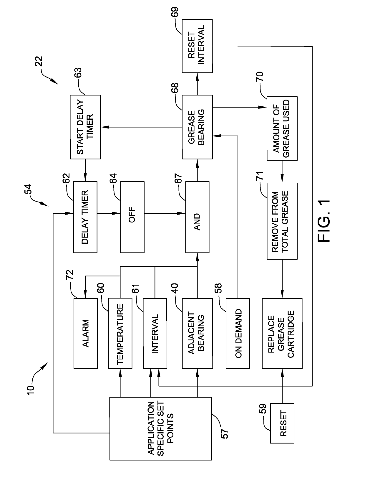
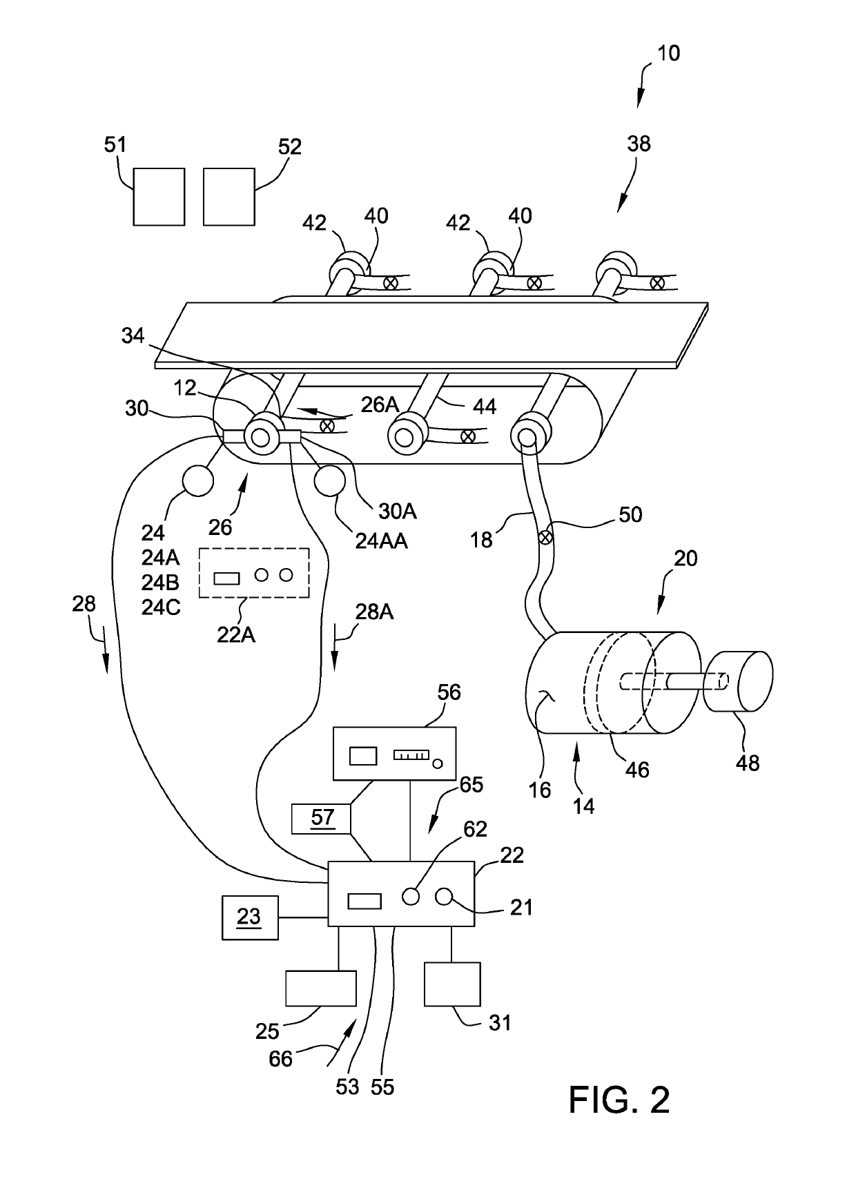
[0069]Referring now to FIGS. 1 and 2 and according to an aspect of the invention, a bearing lubricator 10 for lubricating a lubricated bearing 12 is provided. The bearing lubricator 10 includes a reservoir 14 configured to contain lubricant 16 and a conduit 18 connected to the reservoir 14 and to the lubricated bearing 12. The bearing lubricator 14 also includes a mechanism 20 operably connec...


PUM


Abstract

A bearing lubricator for lubricating a plurality of device bearings in a device includes a solitary monitored bearing and at least one unmonitored bearing. The bearing lubricator includes a reservoir configured to contain lubricant, a plurality of conduits connecting the reservoir to the plurality of bearing, and a mechanism connected to the reservoir for advancing the lubricant from the reservoir to the plurality of device bearings when actuated. The bearing lubricator further includes a solitary sensor for sensing a variable of the monitored bearing and a controller. The controller stores a triggering value of the variable of the monitored bearing. The mechanism advances a substantially identical quantity of the lubricant from the reservoir to each of the plurality of bearings when a signal indicative of the variable is advanced to the controller and when that signal indicates the triggering value of the variable has been met.

Description

CROSS REFERENCE TO RELATED APPLICATION[0001]This application is a continuation-in-part, non-provisional application and claims priority to U.S. Utility patent application Ser. No. 15 / 165,321 filed May 26, 2016 for “BEARING LUBRICATOR, CONTROLLER AND ASSOCIATED METHOD” and published as US 2017 / 0343157 A1 on Nov. 30, 2017, which is hereby incorporated by reference in its entirety.BACKGROUND OF THE INVENTION[0002]The embodiments described herein relate generally to bearing assemblies, and more specifically, to bearing assemblies with a mechanism for adding lubrication to a bearing.[0003]Bearing assemblies permit the relative motion of one component or assembly with respect to another component or assembly. The bearing assembly typically has a first component, for example an inner ring. The inner ring may be fixed to a first component and to a second component, for example, an outer ring that is fixed to a second component. The first component has relative motion, typically to rotate, r...

Claims


Application Information

Patent Timeline
Patent Type & Authority Applications(United States)
IPC IPC(8): F16N29/02F16C33/66
CPCF16N29/02F16C33/6659F16C2233/00F16C33/6625F16N2210/14F16N2270/20F16N2270/70F16C2326/58
Inventor GOSSARD, BRADFORD KYLEFISTROVICH, THOMAS JOHNLEWIS, MATTHEW IVAN
Owner REGAL BELOIT AMERICA
Learn More