

Dispensing pump accessories for preventing the ingress of air and for aiding in alignment
Inactive Publication Date: 2005-02-15
COHEN
View PDF18 Cites 2 Cited by
- Summary
- Abstract
- Description
- Claims
- Application Information
AI Technical Summary
Benefits of technology
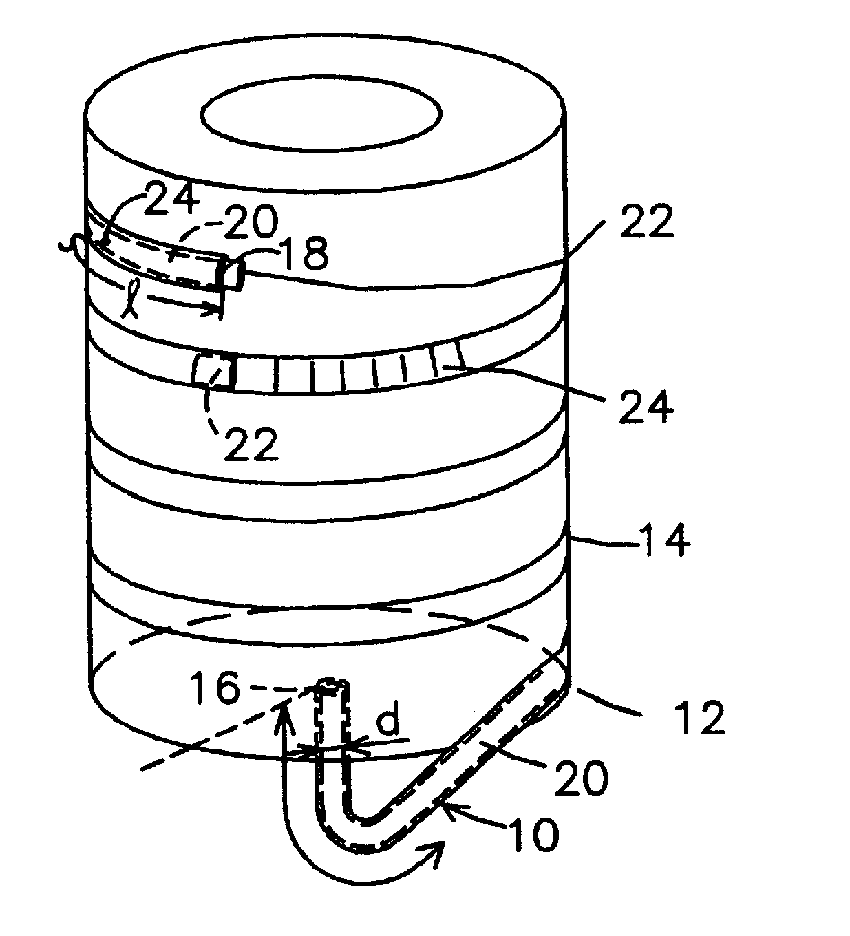
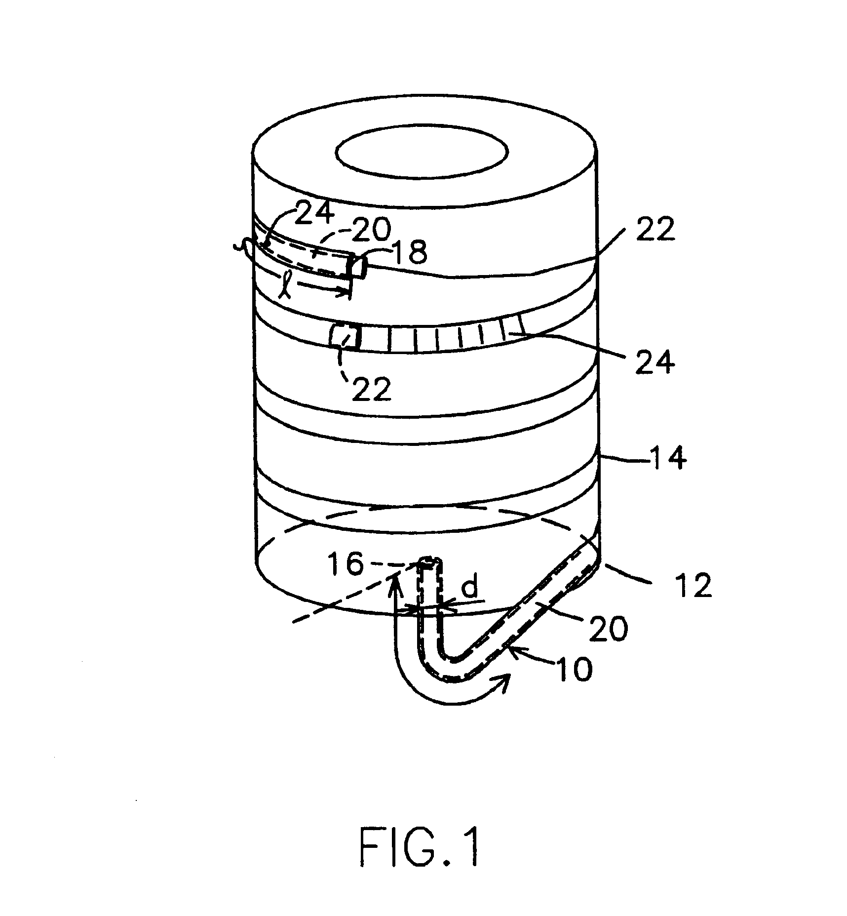
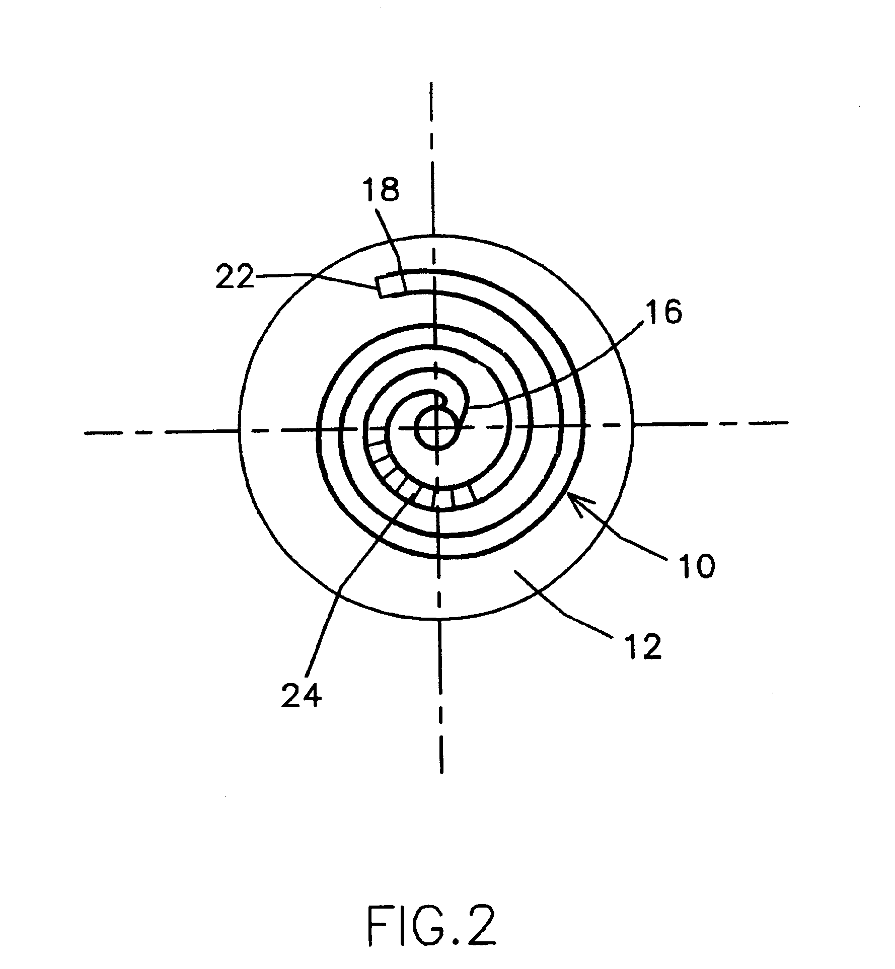
[0010]To prevent the ingress of air into a dispensing pump, in a first embodiment of the invention, a sealed dip tube is provided to replace the liquid reservoir of a dispensing pump. In particular, a dip tube having an elongated member with two ends and an inner passage extending therebetween is provided, in which a liquid supply for the dispensing pump is disposed in the passage. A sealing plug is located in the passage so as to prevent the ingress of air into the liquid. In a preferred embodiment, the sealing plug is slidable in the passage, so as liquid is drawn from the passage, the plug slides behind the liquid as it is drawn and reduces the volume of the passage that is in communication with the dispensing pump. With the arrangement of the first embodiment, the dip tube takes the place of the reservoir, and reduces the likelihood of ingress of air into the pump.
[0012]In a third embodiment of the invention, a liquid reservoir is provided which is preferably cup-shaped with a base and an upstanding side wall. A recess is defined in the base of the reservoir, into which an inlet end of a dip tube extends. The dip tube serves to communicate liquid accommodated in the recess with a dispensing pump. Additionally, a semi-permeable membrane extends across the recess. With the dispensing pump in a gravitationally upright position, liquid contained in the reservoir seeps through the membrane to flood the recess. Upon actuation of the dispensing pump, liquid is drawn through the dip tube from the recess. If the dispensing pump is held in a non-upright position, the semi-permeable membrane restricts flow of the liquid out of the recess—albeit the restriction is not absolute, and liquid eventually seeps through the membrane. The restriction of the semi-permeable membrane, however, makes available a liquid supply for a dose of liquid to be administered by the dispensing pump, with the dispensing pump having any orientation, although the supply will be maintained for a limited time (i.e., before all of the liquid seeps out of the recess). With this arrangement, a volume of liquid is maintained, at least for a limited time, about the inlet end of the dip tube in any orientation of the dispensing pump, so as to limit the ingress of air into the dispensing pump.
[0013]A safety is provided as a fourth embodiment of the invention. In U.S. Pat. No. 5,881,596, a gravity sensitive failsafe mechanism is disclosed in which a dispensing cap and an actuator coact to prevent actuation of the pump with the discharge aperture being oriented outside a predetermined angular range of operation. Although this arrangement is very effective, the inclusion of the actuator as an additional structural element in a dispensing pump may not be desired. With the fourth embodiment of the subject invention, the safety comprises a safety ball; a blind aperture formed in the underside of a nozzle cap with the blind aperture preferably facing in the actuation direction; and, a conical depression partially in registration with the blind aperture that is defined in the dispensing pump body. The safety ball is disposed in the conical depression, and the conical depression is formed such that when a discharge aperture defined in the nozzle cap is oriented beyond a predetermined angular range of operation, the safety ball is urged out of registration with the blind aperture, and when the discharge aperture is oriented within the predetermined angular range of operation, the safety ball is urged into registration with the blind aperture. Where the safety ball is out of registration with the blind aperture, the safety ball prevents depression of the nozzle cap; conversely, where, the safety ball is in registration with the blind aperture, the nozzle cap may be depressed with the safety ball being received within the blind aperture. The predetermined angular range of operation is selected to increase the likelihood that the inlet end of a dip tube is submerged in liquid in a reservoir of the dispensing pump.
[0014]In a fifth embodiment of the invention, a dispensing pump is formed having a pump cylinder disposed partially within a reservoir, with an inlet end of the pump cylinder being in close proximity to the base of the reservoir. The inlet end of the pump cylinder includes an inlet opening which communicates the pump cylinder with liquid contained in the reservoir. No dip tube is used. By locating the inlet end of the pump cylinder in proximity to the base, capillary action of the liquid causes liquid to be drawn to the inlet end / reservoir base interface. To enhance the drawing process, the inlet end may be partially concavely curved away from the base, wherein the concavely curved portion is provided to encourage liquid at the base to feed the pump cylinder equally from all sides. It is also preferred that the pump cylinder be disposed in proximity to a portion of the side wall of the reservoir, and, specifically in proximity to the portion of the side wall located most proximally to the discharge aperture of the dispensing pump. In this manner, the tendency of a party to tilt the dispensing pump forwardly during use is taken advantage of in feeding liquid to the pump cylinder. Also, the pump cylinder / side wall interface allows for capillary action to draw fluid therein. With the dispensing pump in a non-upright position, this capillary action will cause liquid to be drawn up the pump cylinder and to the inlet end thereof. The elimination of the dip tube, and the reliance on capillary action, reduces the likelihood of air being introduced into the dispensing pump.
Problems solved by technology
Thus, a prior art dip tube is not generally responsive to shifts in gravitational orientation of the liquid contained in the dispensing pump reservoir.
Method used
View moreImage
Smart ImageViewing Examples

Examples
fourth embodiment
[0026]FIG. 8 is a schematic of a safety of the subject invention;
[0027]FIGS. 9A and 9B are schematics depicting angular limits of operation where the safety of the fourth embodiment of the subject invention is used with a dispensing pump;
fifth embodiment
[0028]FIG. 10 is a schematic of the subject invention with a pump cylinder being disposed in close proximity to the base of the liquid reservoir;
[0029]FIGS. 11A and 11B are cross-sectional views taken along line x—x of FIG. 10 showing alternate constructions of the pump cylinder;
sixth embodiment
[0030]FIG. 12 is a top plan view of the invention;
[0031]FIG. 13 is a side elevational view of the sixth embodiment of the invention; and,
Login to View More PUM
 Abstract
Accessories are provided for preventing the ingress of air into a dispensing pump (P) and to align a discharge aperture of the dispensing pump with a target, such as an eye (E). A dip tube (10) is disclosed that is sealed with a sealing plug (22) to serve as a liquid reservoir for the dispensing pump. A pliant dip tube (100) is also disclosed to which is mounted an anchor (108) that causes the dip tube (100) to be responsive to gravitational orientation of a dispensing pump (P). In a third embodiment of the invention, a liquid reservoir (200) is formed with a recess (208) that is covered by a semi-permeable membrane (212). The semi-permeable membrane restricts flow in and out of the recess (208) to maintain a supply of liquid (L) about an end (210) of a dip tube (206). In a fourth embodiment, a safety is provided that comprises a safety ball (304), a blind aperture (306) defined in a nozzle cap (302), and a conical depression (308) defined in the dispensing pump (P). The safety ensures that the dispensing pump (P) is only actuated with the discharge aperture (300) of the dispensing pump (P) being oriented within a predetermined angular range of operation (α, β). In a fifth embodiment, a dispensing pump (P) includes a pump cylinder (400) that has one end thereof in close proximity to a base (402) of a liquid reservoir (404). A capillary action is created to cause liquid (L) to be drawn into the inlet opening (406) of the pump cylinder (400). Alignment aids (502; 600) are also disclosed to allow for proper alignment of a discharge aperture (500; 602) of a dispensing pump (P) with the eye (E) of a user.
Description
[0002]This application is a divisional of U.S. application Ser. No. 09 / 806,394, filed on Mar. 29, 2001, now U.S. Pat. No. 6,513,682, which is a 371 of PCT / US99 / 22511, filed on Sep. 29, 1999, which claims benefit of U.S. Provisional Application No. 60 / 102,265, filed on Sep. 29, 1998.FIELD OF THE INVENTION[0003]This invention relates to dispensing pump accessories and, more particularly, to accessories for preventing the ingress of air into a dispensing pump and for aiding in aligning the pump prior to a dispensing procedure.BACKGROUND OF INVENTION[0004]Dispensing pumps are known in the prior art for administering various liquids, including medicants, lotions, oils, perfumes, etc. The majority of dispensing pumps are positive displacement pumps in which the precise size of an administered dose is not considered critical. However, there is a subset of dispensing pumps that satisfy applications where the dose size is considered critical and repeated consistent dosing within narrow toler...
Claims
Login to View More Application Information
Patent Timeline
 IPC IPC(8): A61H35/00A61H35/02A61F9/00B05B11/00
CPCA61F9/0008A61H35/02B05B11/0005B05B11/0027B05B15/005B05B11/0048B05B11/0059B05B11/0037B05B11/30B05B15/30B05B11/0038B05B11/10B05B11/028
InventorCOHENKELLY, NIGEL
OwnerCOHEN