Battery module

a battery module and battery technology, applied in the field of batteries, can solve the problems of secondary degradation influenced by abnormal batteries, and achieve the effect of high degree of safety

Inactive Publication Date: 2012-06-28
PANASONIC INTELLECTUAL PROPERTY MANAGEMENT CO LTD
View PDF2 Cites 97 Cited by
  • Summary
  • Abstract
  • Description
  • Claims
  • Application Information

AI Technical Summary

Benefits of technology

[0015]According to the present disclosure, a high-temperature gas from an abnormal battery can be released to outside a case without an influence on other normal batteries. As a result, a battery module with a high degree of safety can be obtained.

Problems solved by technology

In particular, in a situation where a gas is generated by heat due to, for example, an internal short circuit in a battery and a safety valve actuates to release a high-temperature gas to outside the battery, when adjacent batteries are exposed to this high-temperature gas, normal batteries might also be affected, resulting in the possibility of a secondary degradation influenced by the abnormal battery.

Method used


Image

  • Battery module
  • Battery module
  • Battery module

Examples


first embodiment

Variation of First Embodiment

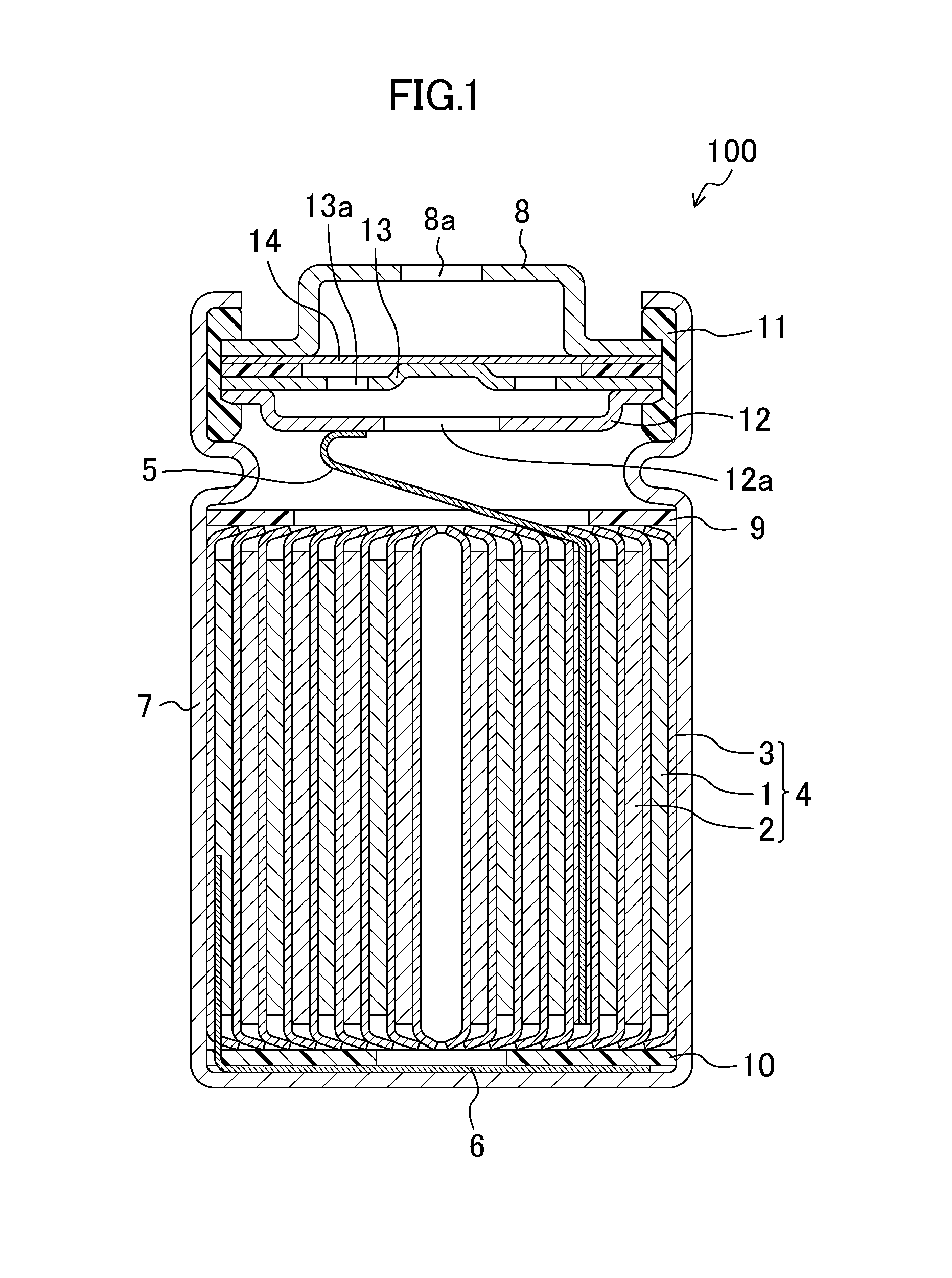
[0071]As illustrated in FIG. 2, in the first embodiment, the exhaust duct 60 is separated from the housing space 50 by a plate disposed at the same sides (i.e., toward the positive electrode terminals or the negative electrode terminals) of the cells 100. This configuration is obtained by arranging the cells 100 in the case 20 with the polarities of the cells 100 oriented in the same direction.

[0072]FIG. 6 is a cross-sectional view schematically illustrating a configuration of the battery module 200 according to a variation of the first embodiment. As illustrated in FIG. 6, this variation is different from the first embodiment in that the cells 100 are arranged with their polarities alternately oriented in opposite directions.

[0073]As illustrated in FIG. 6, the cells 100 are housed in the case 20 in such a manner that the positions of the positive electrode terminals 8 alternate between the top and the bottom, specifically, the positive electrode termina...

second embodiment

[0080]In the first embodiment, the housing space 50 housing the cells 100 and the exhaust duct 60 for releasing a gas from the vents 8a of the cells 100 are separated from each other by the flat plate 30. The flat plate 30 may have a function of electrically connecting the electrodes of the cells 100.

[0081]In this embodiment, this function of the flat plate 30 of electrically connecting the electrodes of the cells 100 will be described. The connection structure among the electrodes of the cells 100 described in this embodiment does not limit the release mechanism described in the first embodiment. In the following description, description of the housing space 50 of the cells 100 and the exhaust duct 60 will not be repeated.

[0082]FIGS. 7(a) and 7(b) are views illustrating a connection structure among the electrodes of the cells 100 connected in a line (hereinafter referred to as a “battery assembly”). Specifically, FIG. 7(a) is a disassembled perspective view, and FIG. 7(b) is an enl...

third embodiment

[0107]In the first embodiment, although the exhaust duct 60 is divided into the first space 61 and the second space 62 by the partition 40, a gas released from the first space 61 to the second space 62 has a temperature equal to or lower than a temperature at which the gas does not react with oxygen, and thus, the possibility of combustion of a gas is eliminated in the second space 62. Accordingly, unlike the first space 61, the second space 62 does not need to have a volume as small as possible for adiabatic expansion, and is allowed to have a relatively large volume as compared to the first space. In other words, an exhaust space corresponding to the second space 62 does not need to be provided in the case 20 housing a plurality of cells 100.

[0108]A battery module according to this embodiment employs a configuration in which a first exhaust space (corresponding to the first space 61) defined by a flat plate 30 placed at the same sides of the cells 100 is provided in a case 20 and ...


PUM

PropertyMeasurementUnit
temperatureaaaaaaaaaa
thicknessaaaaaaaaaa

Abstract

The case 20 housing a plurality of cells 100 is divided, by a circuit board 30 provided at the same sides of the cells 100, into a housing space 50 housing the cells 100 and an exhaust duct 60 for releasing a gas from the vents 8a of the cells 100 to outside the case 20. The vents 8a of the cells 100 communicate with the exhaust duct 60 through openings 30a formed in the flat plate 30. The exhaust duct 60 is divided into a first space 61 and a second space 62 by a partition 40 provided between the flat plate 30 and an external plate 21 of the case 20. The first space 61 communicates with the second space 62 through holes 40a formed in the partition 40.

Description

TECHNICAL FIELD[0001]The present disclosure relates to battery modules in each of which a plurality of batteries are housed in a case, and more particularly to a battery module including a release mechanism for releasing a gas from a battery to outside the case with safety.BACKGROUND ART[0002]Battery packs in each of which a plurality of batteries are housed in a case so as to output a predetermined voltage and have a predetermined capacity are widely used as power sources for various equipment and vehicles. For these batteries packs, a technique of connecting general-purpose batteries in parallel or in series to form modules of battery assemblies each outputting a predetermined voltage and having a predetermined capacity and of variously combining such battery modules to cope with various applications. This module technique enables reduction in size and weight of battery modules by enhancing performance of batteries housed in battery modules, and therefore, has advantages such as i...

Claims


Application Information

Patent Timeline
Patent Type & Authority Applications(United States)
IPC IPC(8): H01M2/12H01M50/213H01M50/284H01M50/289H01M50/35H01M50/502H01M50/505H01M50/512H01M50/522
CPCH01M2/105H01M2/1247H01M2/1252H01M2/204H01M10/503H01M10/5004H01M2/1077H01M2/206H01M2200/00H01M2/12H01M10/5073H01M10/643H01M10/6566H01M10/613Y02E60/10H01M50/213H01M50/383H01M50/35H01M50/502H01M50/522H01M50/284H01M50/512H01M50/505H01M50/289H01M50/204H01M50/367H01M50/358H01M50/30H01M2220/20
Inventor ITOI, TOSHIKIYASUI, SHUNSUKETAKASAKI, HIROSHI
Owner PANASONIC INTELLECTUAL PROPERTY MANAGEMENT CO LTD
Why Eureka
Try Eureka