Compensation for magnetic disturbance due to fluoroscope

a fluoroscope and magnetic field technology, applied in the field of sensing the position, can solve problems such as tracking errors

Active Publication Date: 2012-06-28
BIOSENSE WEBSTER (ISRAEL) LTD
View PDF3 Cites 78 Cited by
  • Summary
  • Abstract
  • Description
  • Claims
  • Application Information

AI Technical Summary

Problems solved by technology

However, disturbances in the magneti...

Method used


Image

  • Compensation for magnetic disturbance due to fluoroscope
  • Compensation for magnetic disturbance due to fluoroscope
  • Compensation for magnetic disturbance due to fluoroscope

Examples


Embodiment Construction

Overview

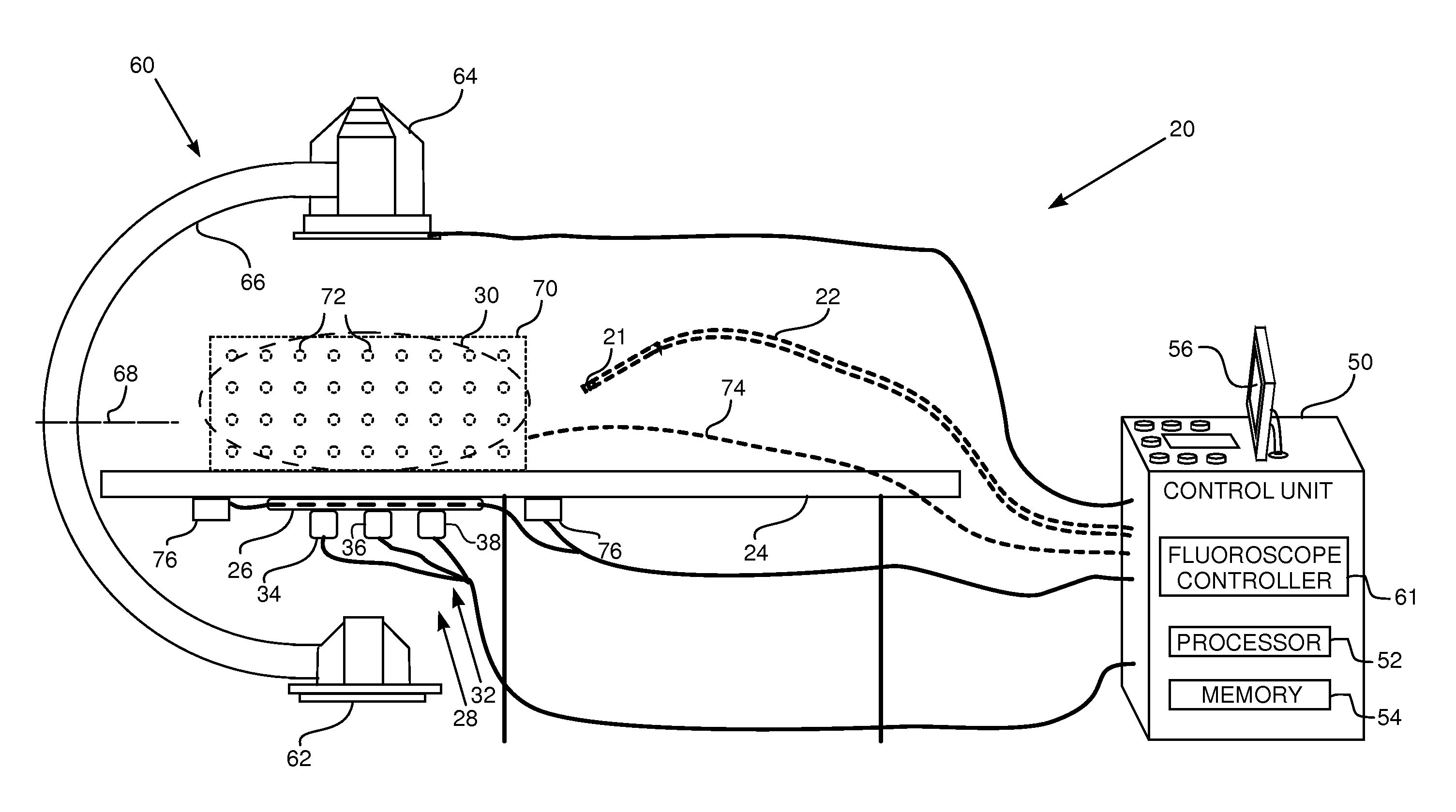
[0067]Embodiments of the present invention provide a method for compensating for perturbations created in a magnetic field in a region. The perturbations are caused by introduction of a perturbing element, typically a metallic component, into a field generated by magnetic transmitters. In order to compensate for the presence of the perturbing element, a reaction field model used by embodiments of the present invention assumes that each magnetic transmitter creates multiple images of the transmitter in the element. The model assumes that each image generates a respective reaction field, which in total act to perturb the field generated by the transmitters.

[0068]Each image may typically be characterized as a combination of multipoles, i.e., dipoles, quadrupoles and / or higher order poles. Characteristics of each image are also dependent, inter alia, on the transmitter field generating the image. The model typically calculates the reaction field from each of the multipolar image...


PUM


Abstract

A method, consisting of generating, using a plurality of magnetic transmitters, a magnetic field in a region and introducing a field perturbing element into the region. The method includes characterizing multiple images of each magnetic transmitter in the field perturbing element, and calculating a reaction magnetic field in the region based on the characterized images. The method further includes positioning a probe in the region and measuring a perturbed magnetic field at the probe, and determining a location of the probe in response to the measured perturbed magnetic field and the calculated reaction magnetic field.

Description

FIELD OF THE INVENTION[0001]The present invention relates generally to sensing the position of an object placed within a living body, and specifically to compensation for magnetic disturbances affecting a sensor of the position.BACKGROUND OF THE INVENTION[0002]A wide range of medical procedures involve placing objects, such as sensors, tubes, catheters, dispensing devices, and implants, within the body. Real-time imaging methods are often used to assist doctors in visualizing the object and its surroundings during these procedures. Some methods track the objects using the object using magnetic fields. However, disturbances in the magnetic field may create errors in the tracking.[0003]U.S. Pat. No. 6,714,008, to Holmes, et al., whose disclosure is incorporated herein by reference, describes a gradiometric measurement methodology for determining magnetic fields of large objects.[0004]U.S. Patent Application 2004 / 0034515, to Bar Tal, et al., whose disclosure is incorporated herein by r...

Claims


Application Information

Patent Timeline
IPC IPC(8): A61B5/05G01B7/14
CPCA61B5/062A61B5/7203A61B5/7217A61B19/5244A61B2560/0223A61B2019/5238A61B2019/5251A61B2019/5255A61B2017/00725A61B2034/2055A61B34/20A61B2090/376A61B2034/2051A61B6/12A61B6/4441A61B6/487A61B6/582A61B6/585A61B6/587
Inventor MONTAG, AVRAM DANBAR-TAL, MEIRBAR-ON, TAL HAIM
Owner BIOSENSE WEBSTER (ISRAEL) LTD
Why Eureka
Try Eureka