Magnetic-disturber detection method and detector, object-localizing method and system, recording medium for these methods

a detection method and detector technology, applied in the field of magnetic disturber detection methods and detectors, can solve the problems of many magnetic disturbers liable to falsify the localization, erroneous localization of objects, and harmful consequences, and achieve the effect of increasing the precision of magnetic disturber detection

Active Publication Date: 2011-04-14
COMMISSARIAT A LENERGIE ATOMIQUE ET AUX ENERGIES ALTERNATIVES
View PDF4 Cites 16 Cited by
  • Summary
  • Abstract
  • Description
  • Claims
  • Application Information

AI Technical Summary

Benefits of technology

[0016]This method is simple to implement because the computation of the direction vectors requires only some multiplications and additions. It can therefore be executed very swiftly and can be applied in “real time”, even if the sensors and the emitter move rapidly relative to one another. Furthermore, it is particularly sensitive. Indeed, a slight disturbance of the direction of one of the direction vectors can result in a major modification of the minimum distance d.
[0028]These embodiments of the detection method furthermore have the following advantages:
[0029]computing the angle between the vectors {right arrow over (n)}1 and {right arrow over (n)}2 increases the precision of detection of the magnetic disturber.

Problems solved by technology

Indeed, if the measured magnetic field used to localize an object is disturbed, then the localizing of the object will be erroneous.
This may have particularly harmful consequences when the localizing method is used in medicine to locate a probe or a catheter within the human body.
Now, in medicine, there are many magnetic disturbers liable to falsify the localization.
These methods use complex computations.

Method used


Image

  • Magnetic-disturber detection method and detector, object-localizing method and system, recording medium for these methods
  • Magnetic-disturber detection method and detector, object-localizing method and system, recording medium for these methods
  • Magnetic-disturber detection method and detector, object-localizing method and system, recording medium for these methods

Examples


Embodiment Construction

[0052]Here below in this description, the characteristics and functions well known to those skilled in the art shall not be described in detail.

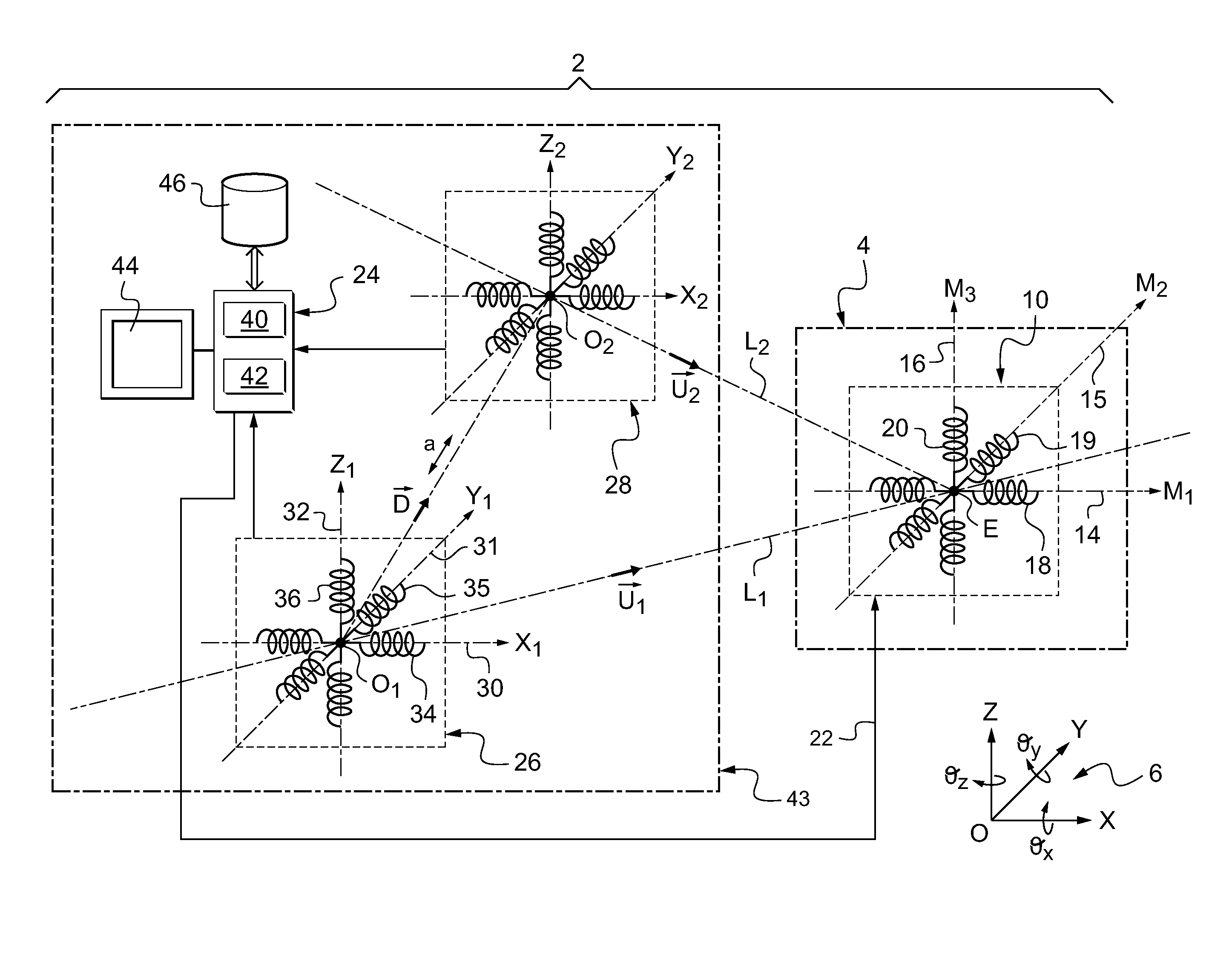
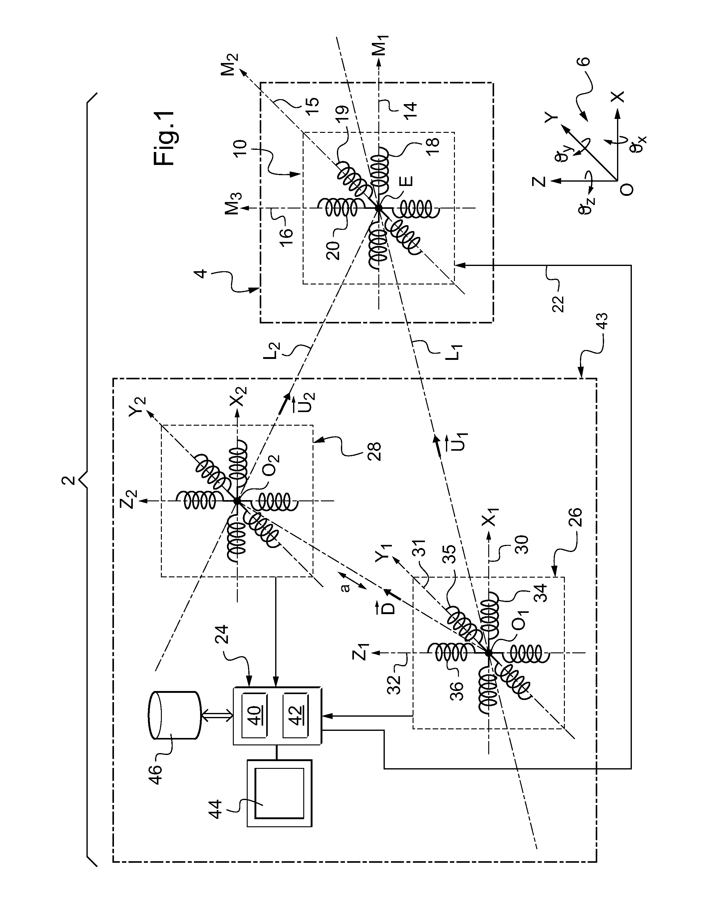
[0053]FIG. 1 represents a system 2 for localizing an object 4 in a referential system 6. For example, the object 4 is a probe or a catheter introduced into the human body. For example, the object 4 is mobile relative to the referential system 6.

[0054]The referential system 6 is a fixed referential with three orthogonal axes X, Y, and Z.

[0055]The localizing of the object 4 in the referential system 6 consists for example in finding its x, y, z position and its θx, θy, θz orientation. The angles θx, θy and θz represent the orientation of the object 4 respectively about the X, Y and Z axes.

[0056]To localize the object 4 in the referential system 6, the object is equipped for example with several magnetic field emitters. To simplify FIG. 1, only one emitter 10 has been shown.

[0057]The emitter 10 is a triaxial emitter emitting a magnetic field al...


PUM


Abstract

This method for detecting a magnetic disturber method comprises:the measurement (52) of the magnetic field emitted by the emitter by at least two triaxial sensors placed at different known positions,, for each sensor, the determining, (54) from the magnetic field measured by this sensor, of the coordinates of a direction vector collinear with an axis passing through the geometrical center of the emitter and the geometrical center of this sensor, the geometrical center of the emitter being the point at which there is located a magnetic field point source which models this emitter and the sensor being capable of being modeled by a point transducer situated at a point where the magnetic field is measured and constituting the geometrical center of this sensor,verification (56;70) that the smallest distance between the axes, each collinear each with one of the direction vectors, is smaller than a predetermined limit, andif this is not the case, the reporting (64) of the presence of a magnetic disturber and, in the contrary situation, not making this report.

Description

BACKGROUND OF THE INVENTION[0001]The invention pertains to a method for detecting a magnetic disturber (or disturbing element) of the magnetic field emitted by an emitter of an at least triaxial magnetic field. The invention also relates to a method and a system for localizing an object and to a medium for recording information to implement these methods.[0002]A magnetic disturber is defined herein as being any object that degrades or deforms the field lines of a magnetic field emitted in proximity. For example, the disturber may be a conductive part. In this case, the degradation of the magnetic field lines is caused by the appearance of eddy currents in the conductive part. The conductive part may be for example a metal part. The disturber may also be a magnetic part such as a paramagnetic or ferromagnetic part.[0003]A triaxial magnetic field emitter emits a magnetic field along three emission axes that are mutually non-collinear. For example, such an emitter is formed by several ...

Claims


Application Information

Patent Timeline
Patent Type & Authority Applications(United States)
IPC IPC(8): G01R33/02
CPCA61B5/06G01V3/104G01V3/08A61B5/062
Inventor BILLERES, MALVINABLANPAIN, ROLAND
Owner COMMISSARIAT A LENERGIE ATOMIQUE ET AUX ENERGIES ALTERNATIVES
Why Eureka
Try Eureka