Heavy duty tire

a technology of heavy duty tires and tread shoulders, applied in the direction of heavy duty vehicles, vehicle components, non-skid devices, etc., can solve the problems of increased edge unit presence, etc., and achieve the effect of inhibiting uneven wear of tread shoulders and improving wet performance at the time of turning

Inactive Publication Date: 2012-07-05
BRIDGESTONE CORP
View PDF7 Cites 12 Cited by
  • Summary
  • Abstract
  • Description
  • Claims
  • Application Information

AI Technical Summary

Benefits of technology

[0017]According to the characteristics of the present invention, it is possible to provide a heavy duty tire in which wet performance at the time of turning is further improved while inhibiting uneven wear of the tread shoulder unit.

Problems solved by technology

However, the formation of a large number of circumferential grooves in the tread shoulder unit increases the presence of edge units.
Because of this, the ground pressure is concentrated at the edge unit, resulting in a problem that the tread shoulder unit is easily worn unevenly.

Method used


Image

  • Heavy duty tire
  • Heavy duty tire
  • Heavy duty tire

Examples


first modification

(5. 1) First Modification

[0047]The configuration of the heavy duty tire according to a first modification is explained with reference to the drawings. FIG. 4(a) is a partial development diagram of a pattern arranged in the tread unit of the heavy duty tire according to the first modification.

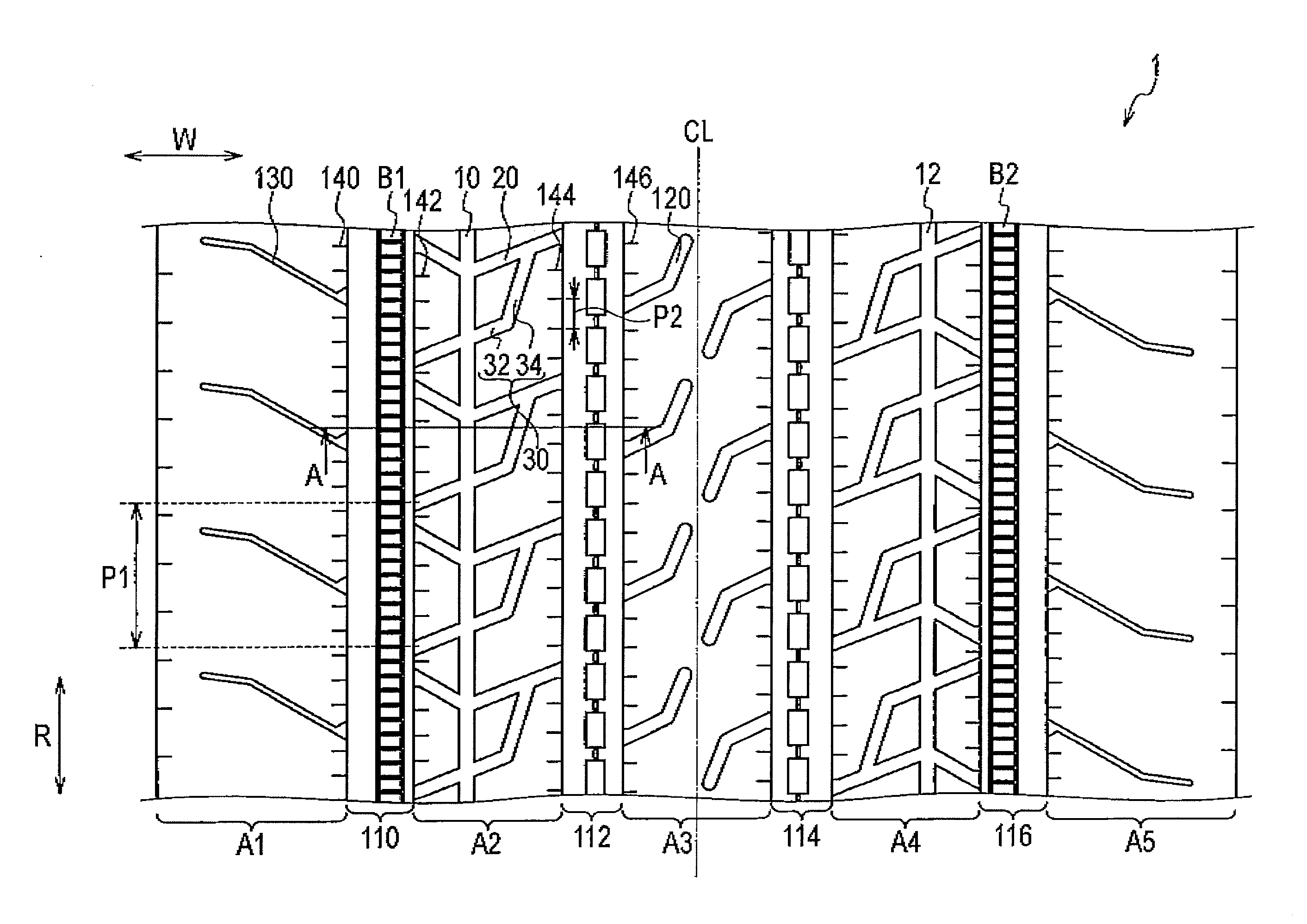
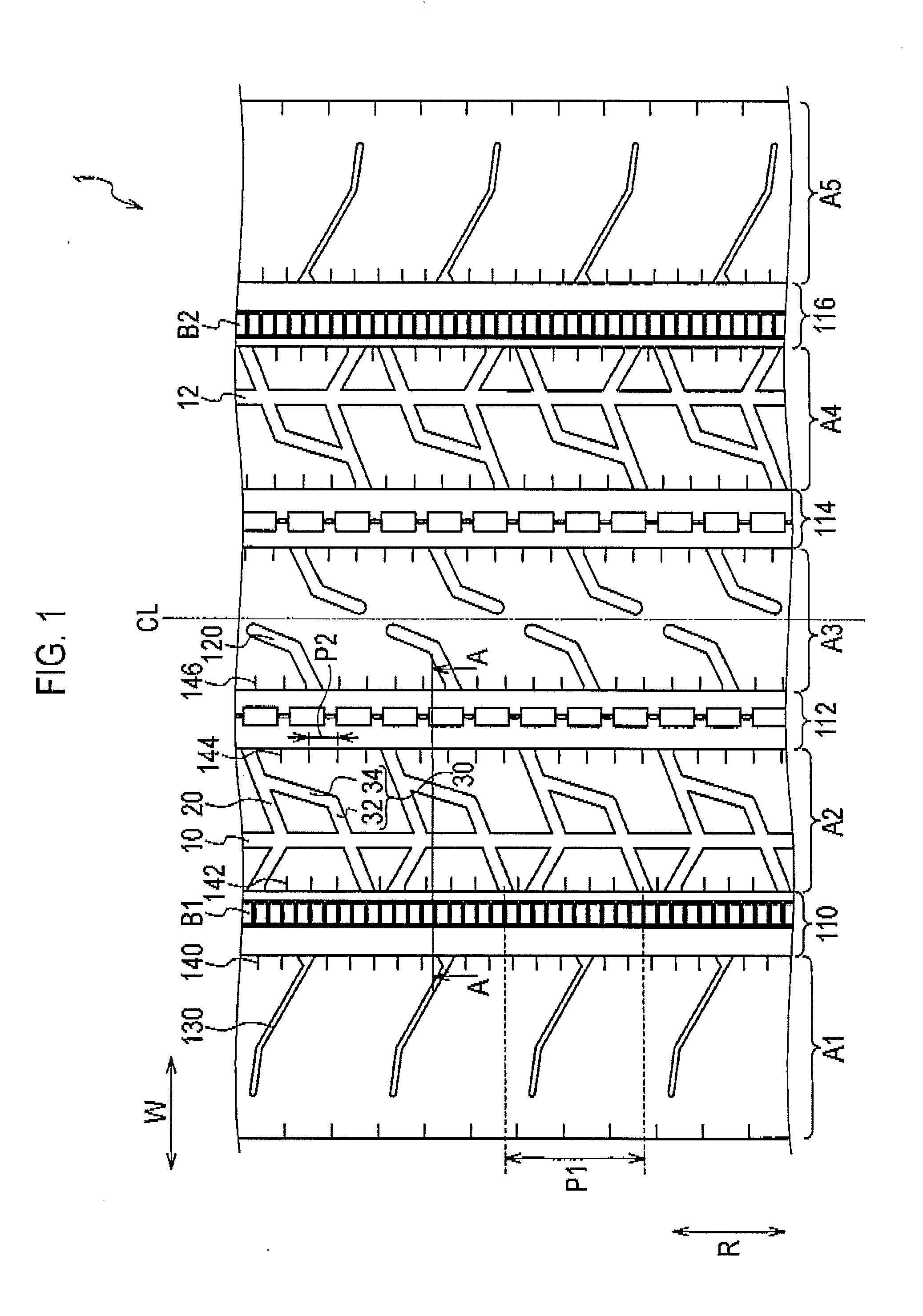
[0048]In the above-mentioned embodiment, the intersectional narrow groove 30 of the heavy duty tire 1 is formed in L shape including the transverse groove 32 extending along the tread width direction W and the longitudinal groove 34 extending along the tire circumferential direction R. As shown in FIG. 4(a), in the first modification, an intersectional narrow groove 30A is formed in linear fashion extending slantingly with respect to the tire circumferential direction R. One end of the intersectional narrow groove 30A communicates to the circumferential groove 110 and the other end communicates to a transverse groove 20A.

second modification

(5. 2) Second Modification

[0049]The configuration of the heavy duty tire according to a second modification is explained with reference to the drawings. FIG. 4(b) is a partial development diagram of a pattern arranged in the tread unit of the heavy duty tire according to the second modification.

[0050]As shown in FIG. 4(b), in the second modification, in the intersectional narrow groove 30B, the transverse groove 32B extending in linear fashion along the tread width direction W and the longitudinal groove 34B extending in linear fashion along the tire circumferential direction R communicate to each other in almost vertical fashion, and thus, the intersectional narrow groove 30B is formed in L shape having a right angle unit.

third modification

(5. 3) Third Modification

[0051]The configuration of the heavy duty tire according to a third modification is explained with reference to the drawings. FIG. 4(c) is a partial development diagram of a pattern arranged in the tread unit of the heavy duty tire according to the third modification.

[0052]As shown in FIG. 4(c), in third modification, the intersectional narrow groove 300 includes a transverse groove 320 extending in linear fashion along the tread width direction W, a transverse groove 32D, and a longitudinal groove 340 extending in linear fashion along the tire circumferential direction R.


PUM


Abstract

A heavy duty tire comprising: a shoulder rib (A1) (shoulder rib (A5)) which is provided to a tread shoulder unit; a second rib (A2) (second rib (A4)) which is adjacent to the shoulder rib (A1) with a circumferential groove (110) (circumferential groove (116)) interposed therebetween and is provided further toward the tire equator side than the shoulder rib (A1); and an uneven wear absorbing rib (B1) (uneven wear absorbing rib (B2)) provided within the circumferential groove (110) and located further toward the inside in the tire radial direction than the tread surfaces of the shoulder rib (A1) and of the second rib (A2). Circumferential narrow grooves (10, 12) having a smaller width than the circumferential grooves (110, 116) are formed in the second ribs (A2, A4). Each circumferential narrow groove (10, 12) is formed in such a manner that, when the tire is mounted on the vehicle, the circumferential groove (10, 12) is located on the outer side of the tire with reference to the center of the second rib (A2, A4) in the tread width direction.

Description

TECHNICAL FIELD[0001]The present invention relates to a heavy duty tire provided with a shoulder rib that is arranged in a tread shoulder unit and extends in the tire circumferential direction, a center side rib that is adjacent to the shoulder rib through a circumferential groove, is arranged nearer to a tire equator line than the shoulder rib, and extends in the tire circumferential direction, and an uneven wear absorbing rib that is arranged inside the circumferential groove, extends in the tire circumferential direction, and is located inwardly in a tire radial direction from the tread of the shoulder rib and the center side rib.BACKGROUND ART[0002]Conventionally, in heavy duty tires which are mounted on vehicles like a truck or a bus mostly operating on straight routes, in order to prevent the uneven wear of a tread shoulder unit, specifically, a shoulder rib and the like which configure the rib of the tread shoulder unit, there is widely used a method to arrange an uneven wear...

Claims


Application Information

Patent Timeline
Patent Type & Authority Applications(United States)
IPC IPC(8): B60C11/11B60C11/117
CPCB60C2200/06B60C2011/0397B60C2011/0383B60C2011/0381B60C2011/133B60C11/04B60C11/042B60C2011/036B60C2011/0362B60C2011/0348B60C2011/0351B60C2011/039B60C2011/0386B60C2011/1245B60C2011/0374B60C11/047
Inventor SUGANUMA, AKIRA
Owner BRIDGESTONE CORP
Why Eureka
Try Eureka