Supercharge Your Innovation With Domain-Expert AI Agents!

Device for assisting the installation and de-installation of an awning

a technology for assisting the installation and de-installation of awnings, which is applied in the direction of sunshades, door/window protective devices, manufacturing tools, etc., can solve the problems of only transmitting the pull cord, the pull cord system is susceptible to jamming in the awning rail, and the disadvantages are the sam

Inactive Publication Date: 2012-07-05
CARMAN ENTERPRISE
View PDF8 Cites 0 Cited by
  • Summary
  • Abstract
  • Description
  • Claims
  • Application Information

AI Technical Summary

Benefits of technology

[0009]Therefore, it is an object of the invention to provide a device, which simplifies the installation and de-installation of an awning to and from an awning rail, is not susceptible to jamming in the awning rail and can be protected against detrimental environmental influences.

Problems solved by technology

However, the disadvantages are the same as on the pull cord systems disclosed in the other cited publications.
Moreover, pull cord systems are susceptible for jamming in the awning rail or even for brake down.
Moreover, a pull cord can only transmit pulling forces because they are not so stiff and rigid enough for transmitting pushing forces, which enables de-installation of the awning.

Method used


Image

  • Device for assisting the installation and de-installation of an awning
  • Device for assisting the installation and de-installation of an awning
  • Device for assisting the installation and de-installation of an awning

Examples


first embodiment

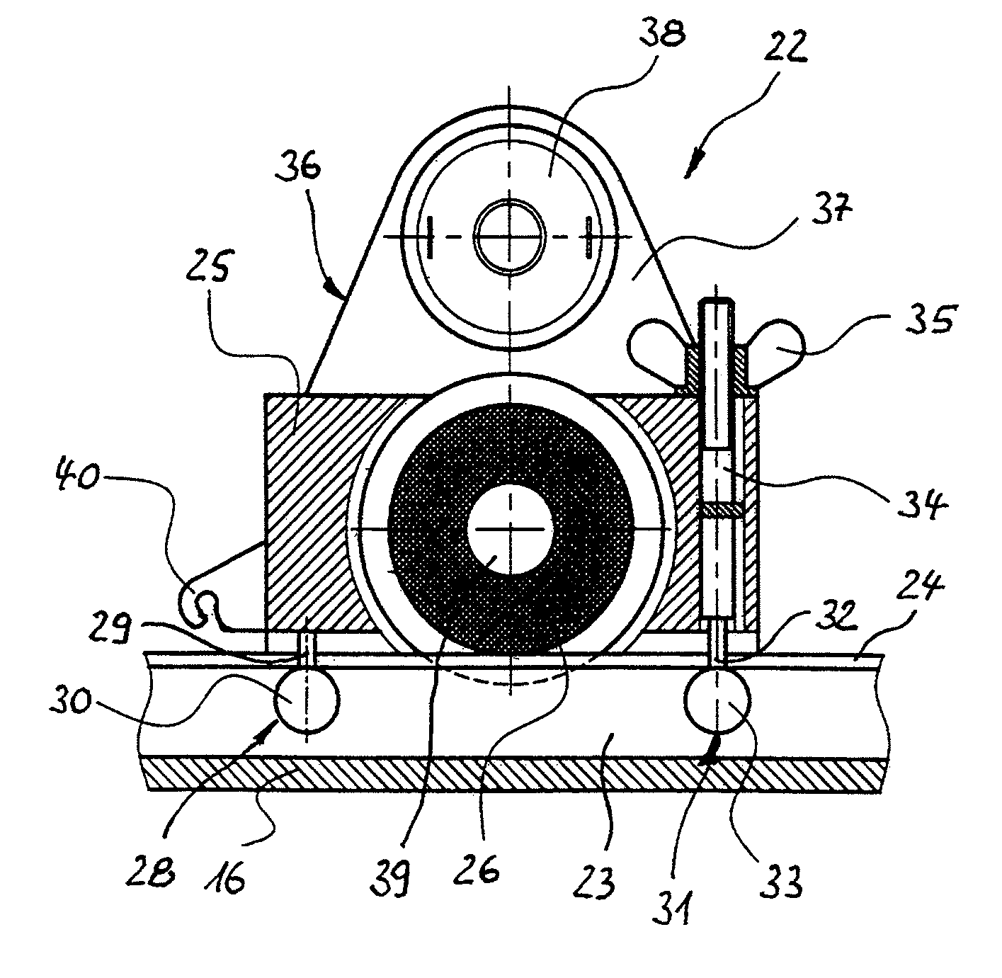
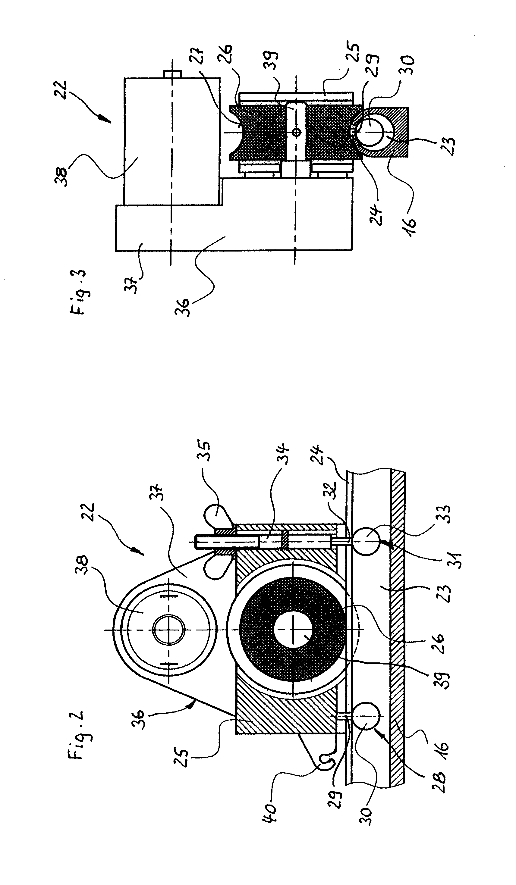
[0041]FIGS. 2 and 3 show the device 22 mounted on the awning rail 16. As particularly recognizable in FIG. 3, the awning rail 16 encloses a free channel 23 with a round cross section, which is open to the outside about a small slot 24 extending in longitudinal direction of the awning rail 16 and constituting a C-profile. The device 22 comprises a sliding body 25 being outside of the awning rail 16. A driving wheel 26 is disposed within the sliding body 25 having a concave rolling surface 27 at its circumference, the radius of which is adapted to the radius of the outer surface of the awning rail 16. The driving wheel 26 consists of an elastomeric material like rubber, and its rolling surface 27 is in frictional contact with the outer surface of the awning rail 16.

[0042]At the rear end of the sliding body 25 and at its bottom, a first guiding element 28 is projecting from the sliding body 25 through the slot 24 into the channel 23 of the awning rail 16. The guiding element 28 consist...

second embodiment

[0052]FIGS. 8 and 9 show a device 42 according to the present invention placed on the awning rail 16. It has a free channel 23 with a round cross-section and a small slot 24 extending in longitudinal direction of the awning rail 16 and constituting a C-profile with side walls 43, 44. The device 42 comprises a sliding body 45, wherein a driving wheel 46 is disposed having a cylindrical rolling surface 47 at its circumference. Also in this case, the driving wheel 46 consists of an elastomeric material like rubber, and its rolling surface 47 is in frictional contact with the outer surface of the awning rail 16, but in this embodiment in contact with the outer surface of its side wall 43.

[0053]In the middle of the sliding body 45 right above the awning rail 16, a single guiding element is projecting from the sliding body 45 through the slot 24 into the channel 23 of the awning rail 16. The guiding element 48 consists of a guide bar 49 guided by the edges of the awning rail 16 forming th...


PUM

PropertyMeasurementUnit
Displacementaaaaaaaaaa

Abstract

The invention relates to a device (22, 42, 72) for assisting the installation and de-installation of an awning (19) at an awning rail (16); the device (22, 42, 72) has a connecting element (40, 73-75) for connection with the awning (19) and a motor (38, 62) for moving the edge of the awning (19) along the awning rail (16);the device (22, 42, 72) comprises a sliding body (25, 45) for sliding the device (22, 42, 72) along the awning rail (16) in a sliding direction; the motor (38, 62) is located on or in the sliding body (25, 45);a driving wheel (26, 46) is disposed on the sliding body (25, 45) and is driven by the motor (38, 62) and arranged so that it contacts the outside of the awning rail (16) when the device (22, 42, 72) is placed on the awning rail (16).

Description

CROSS-REFERENCE TO RELATED APPLICATIONS AND CLAIM TO PRIORITY[0001]This application is related to application No. 11 150 255.5, filed Jan. 5, 2011, in the European Patent Office, the disclosure of which is incorporated herein by reference and to which priority is claimed.FIELD OF THE INVENTION[0002]The invention refers to a device for assisting the installation and de-installation of an awning at an awning rail fixed on a wall for example of a vehicle like a caravan, the awning rail having a C-profile with a slot extending in its longitudinal direction and being destined for the reception of a beading provided at an edge of the awning. The device has a connecting element for connection with the awning and a motor for moving the edge of the awning along the awning rail, wherein the motor is combined with a control system for starting and stopping the motor.BACKGROUND OF THE INVENTION[0003]In general, awnings consist of tent-like structures made of flexible material such as canvas or ...

Claims


Application Information

Patent Timeline
IPC IPC(8): B23P19/04E04F10/02
CPCE04H15/08Y10T29/53126E04F10/02E04F10/0662
Inventor LI, XIAN WEIZHENG, LI
Owner CARMAN ENTERPRISE
Features
  • R&D
  • Intellectual Property
  • Life Sciences
  • Materials
  • Tech Scout
  • Unparalleled Data Quality
  • Higher Quality Content
  • 60% Fewer Hallucinations
Learn More