Capacitive touch display panel

a capacitive touch display and display panel technology, applied in the field of can solve the problems of affecting the display performance of the capacitive touch display panel, affecting the thickness level, and increasing the manufacturing cost, so as to improve the light reflection problem, the effect of improving the light reflection problem and avoiding the increase of manufacturing cost and the thickness level

Active Publication Date: 2012-07-05
AU OPTRONICS CORP
View PDF6 Cites 33 Cited by
  • Summary
  • Abstract
  • Description
  • Claims
  • Application Information

AI Technical Summary

Benefits of technology

[0006]It is one of the objectives of the present invention to provide a capacitive touch display panel for improving the light reflection problem caused by the materials of the bridge lines in the capacitive touch display panel.
[0013]In the present invention, the patterned low reflective layer is employed to improve the light reflection problem caused by the materials of the bridge lines in the capacitive touch display panel. Therefore, the display performance of the capacitive touch display panel may not be affected, and the manufacturing cost and the thickness level may not be affected also.

Problems solved by technology

However, the display performance of the touch display panel may be affected because reflection light may be generated from the metal materials of the bridge line.
An anti-reflection sheet may be attached on the touch display panel to reduce the reflection affect generated by the metal bridge lines, but the additional problems are higher manufacturing cost and thicker total thickness.

Method used


Image

  • Capacitive touch display panel
  • Capacitive touch display panel
  • Capacitive touch display panel

Examples


first embodiment

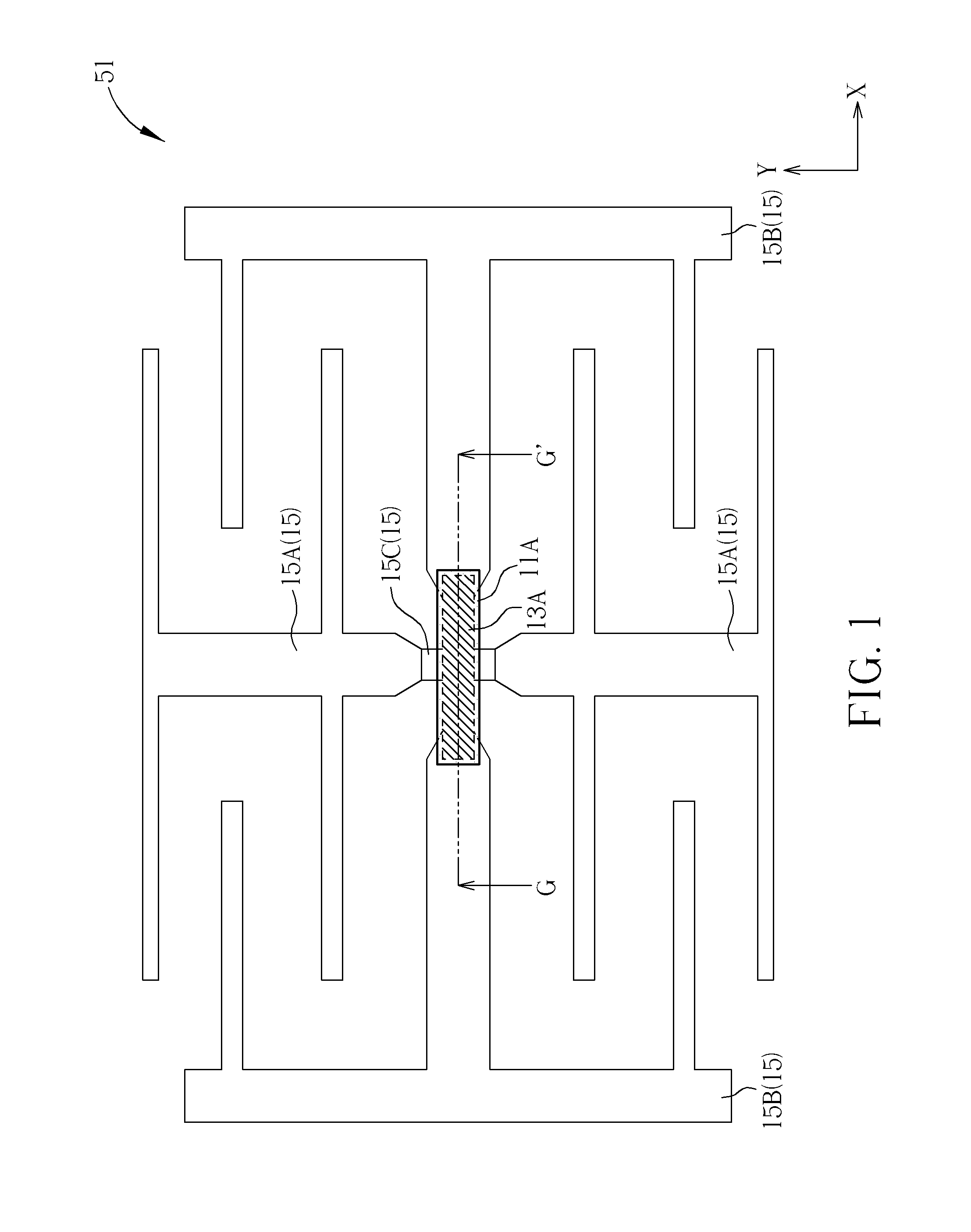
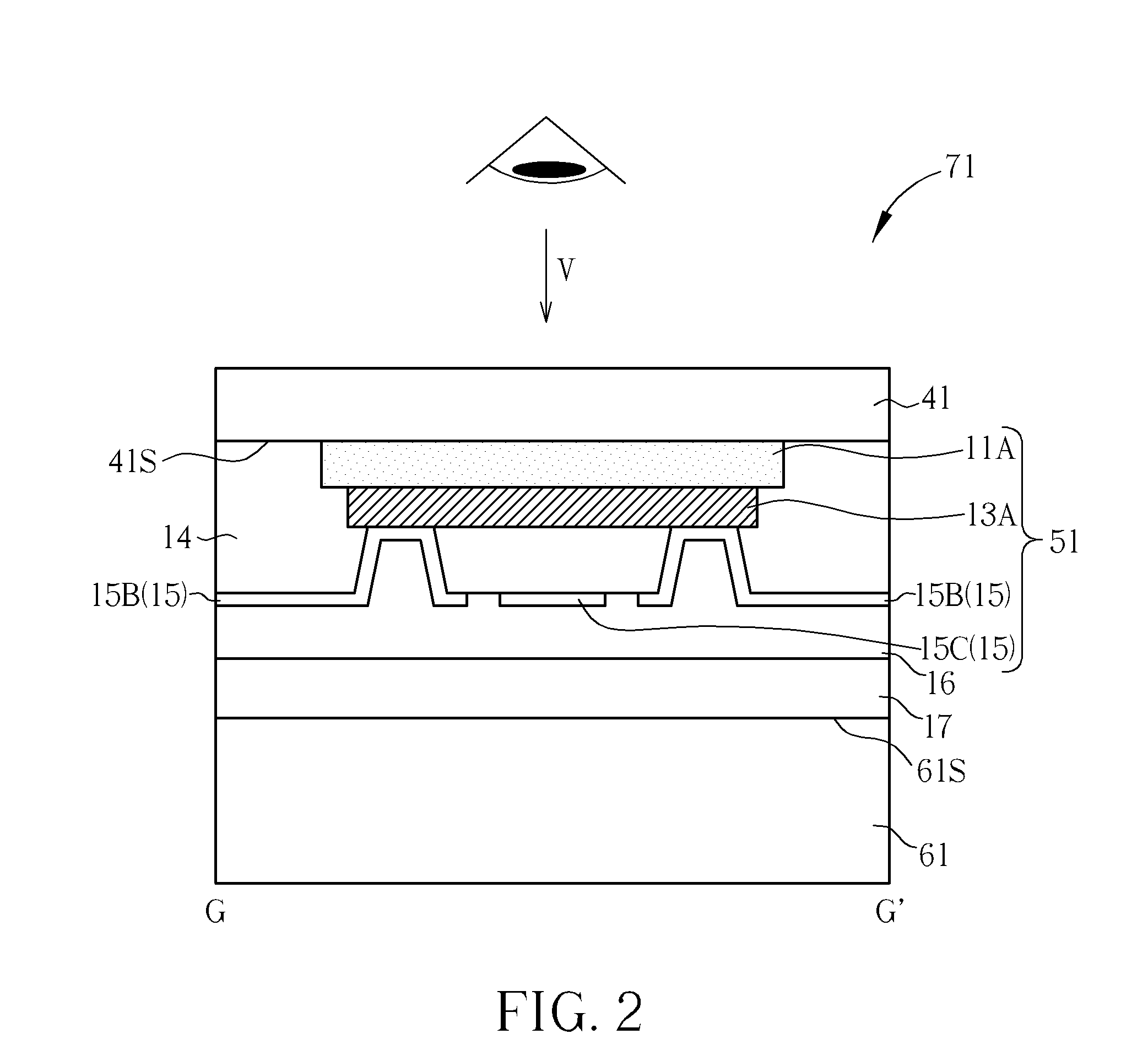
[0027]Please refer to FIG. 3, and refer to FIG. 1 together. FIG. 1 is a schematic diagram illustrating a top view of a capacitive touch display panel according to the second preferred embodiments of the present invention. FIG. 3 is a schematic diagram illustrating is a cross-sectional view of a capacitive touch display panel along a line G-G′ in FIG. 1 according to the second preferred embodiment of the present invention. As shown in FIG. 1 and FIG. 3, the capacitive touch display panel 72 includes a display panel 61, an outer substrate 41, a first insulating layer 14, a second insulating layer 12, a passivation layer 16, an adhesive layer 17, and a capacitive touch device 51. The display panel 61 has a display surface 61S, and the outer substrate 41 is disposed on the display surface 61S of the display panel 61. In this embodiment, the display panel 61 may include a liquid crystal display panel, an electroluminescent display panel, an electrophoretic display panel, or a plasma disp...

third embodiment

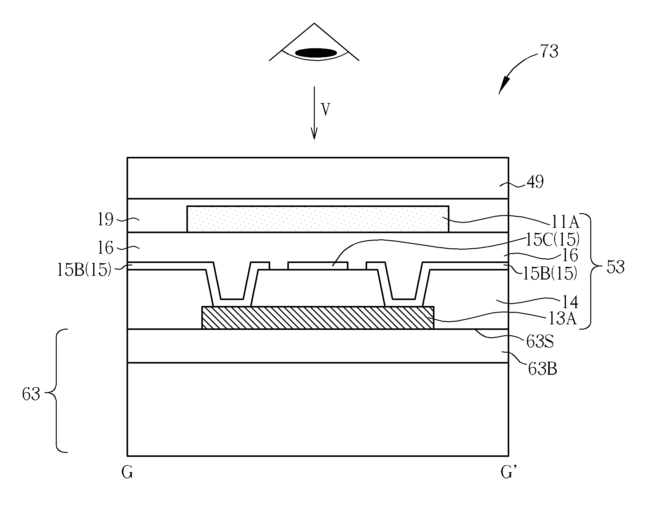
[0030]Please refer to FIG. 6, and refer to FIG. 4 together. FIG. 4 is a schematic diagram illustrating a top view of a capacitive touch display panel according to the fourth preferred embodiment of the present invention. FIG. 6 is a schematic diagram illustrating is a cross-sectional view of a capacitive touch display panel along a line G-G′ in FIG. 4 according to the fourth preferred embodiment of the present invention. As shown in FIG. 4 and FIG. 6, in this embodiment, the capacitive touch display panel 74 includes a display panel 63, a capacitive touch device 53, an auxiliary substrate 44, and a first adhesive layer 18. The display panel 63 includes an upper substrate 63B and a display surface 63S. In this embodiment, the display panel 63 may include a liquid crystal display panel, an electroluminescent display panel, an electrophoretic display panel, or a plasma display panel, but the present invention is not limited to this. The auxiliary substrate 44 is disposed between the di...


PUM


Abstract

A capacitive touch display panel includes a display panel, an outer substrate, and a capacitive touch device. The capacitive touch device is disposed between the outer substrate and the display panel. The capacitive touch device includes a plurality of first transparent electrodes, at least one transparent bridge line, a plurality of second transparent electrodes, at least one non-transparent bridge line, and at least one patterned low reflective layer. The patterned low reflective layer is disposed on an opposite side of the non-transparent bridge line with respect to the display panel. The patterned low reflective layer and the non-transparent bridge line are overlapped to each other in a vertical projective direction.

Description

BACKGROUND OF THE INVENTION[0001]1. Field of the Invention[0002]The present invention relates to a capacitive touch display panel, and more particularly, to a capacitive touch display panel with a patterned low reflective layer.[0003]2. Description of the Prior Art[0004]The touch panel has been widely used in the input interfaces of the instruments for its properties such as the great interaction between machines and humans. In recent years, more consumer electronics, such as mobile phones, GPS navigator systems, tablet computers, laptop computers, and personal digital assistances (PDA) are employed with touch display panels.[0005]There are many diverse technologies of touch panel, and the resistance touch technology, the capacitive touch technology and the optical touch technology are the main touch technologies. The capacitive touch technology has become the mainstream touch technology for the high-end and the mid-end consumer electronics, because the capacitive touch panel has ad...

Claims


Application Information

Patent Timeline
Patent Type & Authority Applications(United States)
IPC IPC(8): G06F3/045
CPCG06F3/044G06F3/0412G06F3/0446G06F3/0443
Inventor KUO, CHUN-KU
Owner AU OPTRONICS CORP
Why Eureka
Try Eureka