Optical pickup apparatus

a technology of optical pickup and optical head, which is applied in the manufacture of optical head, data recording, instruments, etc., can solve the problems of large number of construction parts and respective parts, the effect of avoiding the decrease of s/n, high efficiency and small siz

Inactive Publication Date: 2008-07-01
RICOH KK
View PDF24 Cites 4 Cited by
  • Summary
  • Abstract
  • Description
  • Claims
  • Application Information

AI Technical Summary

Benefits of technology

[0063]It is still another object of the present invention to provide an optical pickup apparatus having a small-sized and simplified optical system of high efficiency for utilizing the light rays.
[0064]It is still another object of the present invention to provide a small-sized and light-weight optical pickup apparatus capable of performing high-speed seeking operation.
[0065]It is still another object of the present invention to provide an optical pickup apparatus capable of avoiding the decrease of S / N of the properly detected signal.
[0066]It is still another object of the present invention to realize an optical system which is extremely small-sized, easy for operating, and in which the variation of the signal due to the positional shift between the respective optical parts is very small.

Problems solved by technology

Conventionally, as mentioned heretofore, there exists some extent of limitation in small-sizing the optical system, in order to completely separating the optical path of the illuminating light rays and that of the detecting light rays by use of the PBS (polarized light beam splitter).
And further, although it has been already proposed to separate the light rays flux by utilizing the hologram, there existed some problems to be solved in the efficiency of utilizing the light rays.
The defect of the optical system in the conventional optical pickup device as mentioned before is that the number of the construction parts is large and the respective parts become large-sized.
Nevertheless, the light utilizing efficiency is not so well.
Since the signal detecting optical system 207 is separatedly provided in order to reproduce the signal in such manner, there arise several problems to be solved that the number of the optical parts employed is increased and that the space for the optical system is large-sized, and further, that the weight of the optical pickup portion is also increased and thereby the high-speed seeking operation cannot be performed.
Since the signal level of the flaring light rays is equal to or more than the level of the signal component regularly (properly) detected by the light-receiving elements; 219a and 219b, there arises a problem to be solved that it is impossible to avoid the S / N-level-down of the properly detected signal.
This is also a problem to be solved.

Method used


Image

  • Optical pickup apparatus
  • Optical pickup apparatus
  • Optical pickup apparatus

Examples


first embodiment

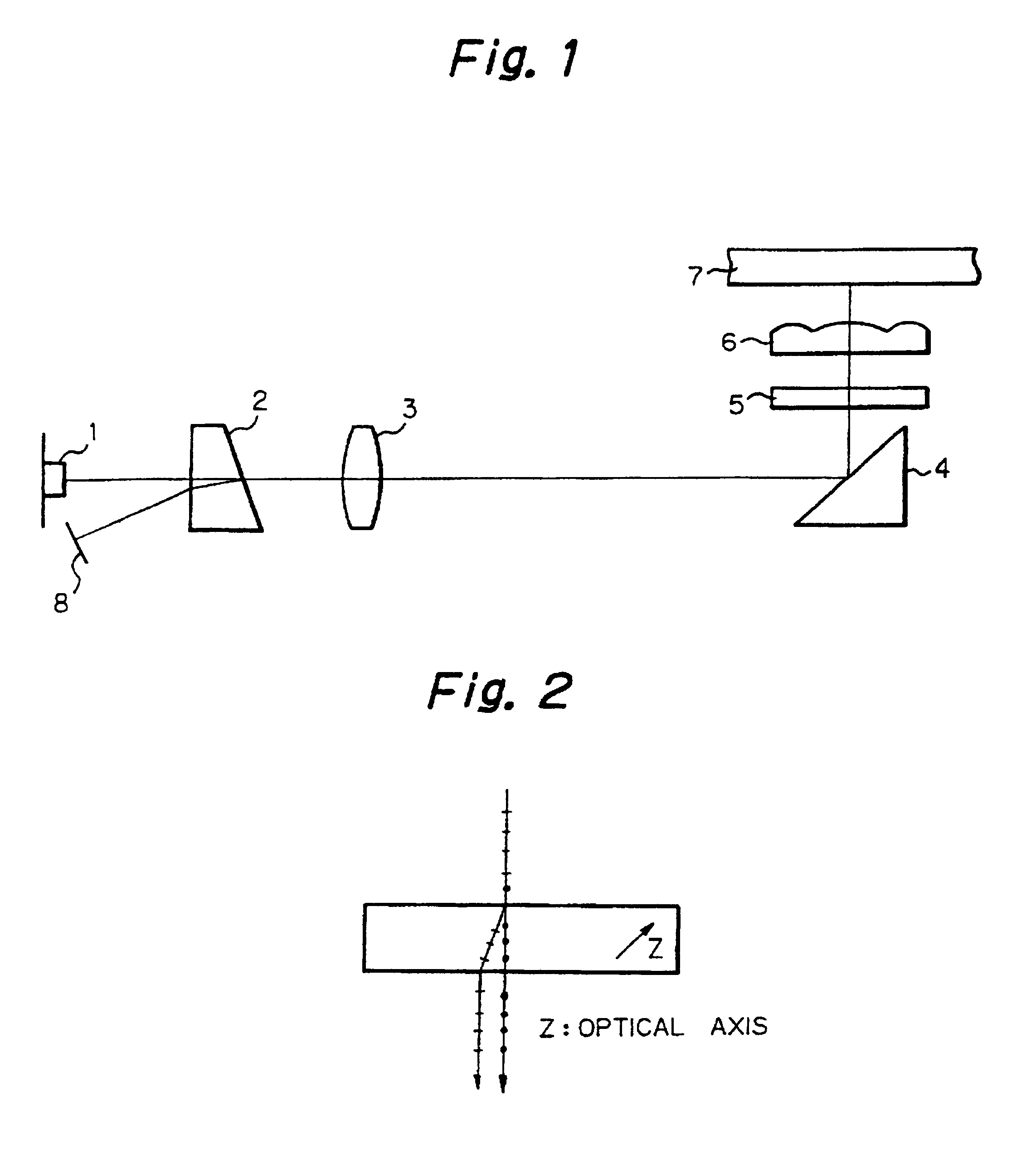
[0146]FIG. 1 is a construction diagram for explaining the optical pickup apparatus according to the present invention. In FIG. 1, the reference numeral 1 represents a semiconductor laser (LD), 2 a birefringent crystal, 3 a coupling lens, 4 a polarizing mirror, 5 a quarter-wave (λ / 4) plate, 6 an objective lens, 7 an optical recording medium, and 8 a light-receiving element (PD).

[0147]The linearly polarized divergent light rays emitted from the semiconductor laser 1 pass through the complex refraction crystal 2, and are converted to the parallel light rays by the coupling lens 3, and further are deflected by the deflecting mirror 4. The light rays deflected by the deflecting mirror 4 are converted to the circularly-polarized light rays by the quarter-wave (λ / 4) plate 5 and focused on the recording surface of the optical recording medium 7 by the objective lens 6. The light rays flux reflected on the recording surface are made parallel again by the objective lens 6 and the same are con...

second embodiment

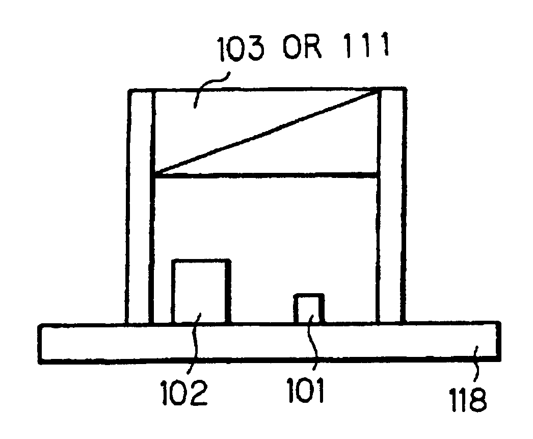
[0155]FIGS. 5 and 6 are construction diagrams showing the other embodiment (second embodiment) of the optical pickup apparatus according to the present invention. In FIG. 5, the reference numeral 11 represent a semiconductor laser (LD) package, 12 an LD chip, 13 a light-receiving element (PD), and 14 a birefringent crystal.

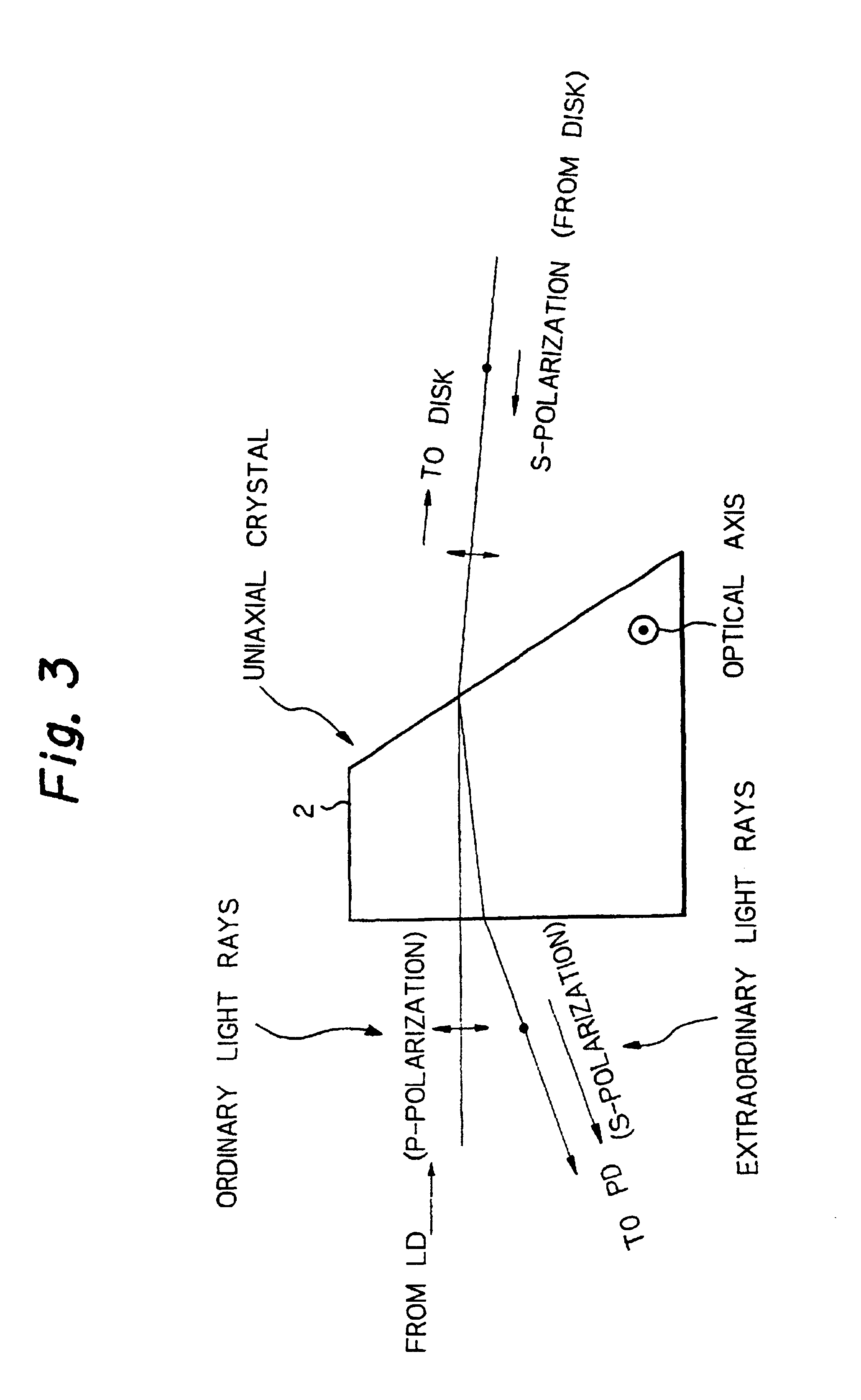
[0156]The PD 13 is accommodated in the LD package 11. The separation distance of the LD chip 12 and the PD 13 can be determined from the parameters; the refractive index and the thickness of the complex refraction crystal, and the angle of the incident light rays. For instance, in case that the parallel plain plate made of the birefringent material of the thickness d as shown in FIG. 6 is disposed slantedly by θ for the optical axis, the separation distance can be expressed as mentioned below.

[0157]Assuming that the incident angle to the birefringent material is α, the refractive index of the refraction line of the ordinary light rays in the birefringent material ...

third embodiment

[0160]FIG. 7 is a construction diagram for explaining the other embodiment (third embodiment) of the optical pickup apparatus according to the present invention. In FIG. 7, the reference numeral represents a birefringent crystal, and same reference numeral is attached to the portion executing the same function as that of the optical pickup apparatus shown in FIG. 5. The birefringent crystal 15 is employed as the window member of the LD package 11 for both of the LD chip and the PD 13.


PUM

PropertyMeasurementUnit
compass direction angleaaaaaaaaaa
timeaaaaaaaaaa
timeaaaaaaaaaa

Abstract

Small-sized and light-weighted optical pickup apparatus capable of eliminating the effect due to the flaring light rays and performing the signal detection of high reliability is provided.
In the apparatus, the quarter-wave (λ/4) plate and the reflection-type birefringent prime provided with the deflecting function of deflecting the reflection light rays reflected on the optical information recording medium and the light rays flux separating function of separating the reflected light rays from the outgoing light rays are disposed in the optical path between the semiconductor laser constructing the optical pickup portion and the objective lens, and the light-receiving element for receiving the reflection light rays from the optical information recording medium which are defleced and separated by the reflection-type birefringent prism is disposed on a single (same) substrate together with the semiconductor laser.

Description

[0001]This is a continuation of application Ser. No. 08 / 311,050 filed Sep. 23, 1994 now U.S. Pat. No. 5,694,385.BACKGROUND OF THE INVENTION[0002]1. Field of the Invention[0003]The present invention relates to optical pickup apparatuses employed for the optical disk drive, in particular, an optical pickup apparatus capable of constructing an optical systems nearly identifying the optical path of illuminating light rays and the other optical path of detecting light rays by use of a light rays flux separating element consisting of birefringent (complex refraction) crystal, another optical pickup apparatus which is small-sized and has a small number of employed parts, and still another optical pickup apparatus executing information record and reproduction and further executing focus servo and tracking servo.[0004]2. Description of the Related Art[0005]Concerning the documents respectively describing the technologies in relation to the first group of the present invention, there exist so...

Claims


Application Information

Patent Timeline
Patent Type & Authority Patents(United States)
IPC IPC(8): G11B7/00G11B7/12G11B7/135
CPCG11B7/1356G11B7/123G11B7/1359G11B7/22G11B11/10543
Inventor TAKAHASHI, YOSHITAKAAKIYAMA, HIROSHIEMOTO, MASAMI
Owner RICOH KK
Why Eureka
Try Eureka