
Control and method of a starter motor for a starter device

a starter motor and control method technology, applied in the direction of engine starters, control systems, electric generator control, etc., can solve the problems of reducing the reliability of the switching device during switching, and no longer achieving the relay coil current necessary for reliable switching, so as to improve the energization stability of the starter motor. , the effect of improving the energization stability

Inactive Publication Date: 2012-07-12
ROBERT BOSCH GMBH
View PDF22 Cites 4 Cited by
  • Summary
  • Abstract
  • Description
  • Claims
  • Application Information

AI Technical Summary

Benefits of technology

[0009]In accordance with the present invention, a control is designed to be in operative contact with a testing device for checking a switching state of an switching device, and to have an adapter for adapting the energization of the switching device. The switching device is checked for proper function with the aid of the testing device. The energization of the starter motor is thus reliably improved. The adapter accordingly responds to a result of the mentioned test by varying the energization of the switching device. Preferably, a switching module functioning as an adapter, which has at least one additional parallel current path for controlling current, is adapted to the actual switching state of the switching device. Thus, an increase in the energization stability of the starter motor may be achieved overall with the aid of reliable switching states.

Problems solved by technology

For this purpose, a high electrical power, in particular a high current, may be necessary so that the start of the internal combustion engine results in a voltage drop of a battery-operated vehicle electrical system.
In such a case, the switching device has not switched reliably, which may be attributed, in particular, to a voltage drop in the vehicle electrical system of the motor vehicle, which reduces the reliability of the switching device during switching.
In particular, in the case of a starter relay as the switching device, the relay coil current necessary for reliable switching is no longer achieved during a voltage drop.

Method used


Image

  • Control and method of a starter motor for a starter device
  • Control and method of a starter motor for a starter device
  • Control and method of a starter motor for a starter device

Examples


Embodiment Construction

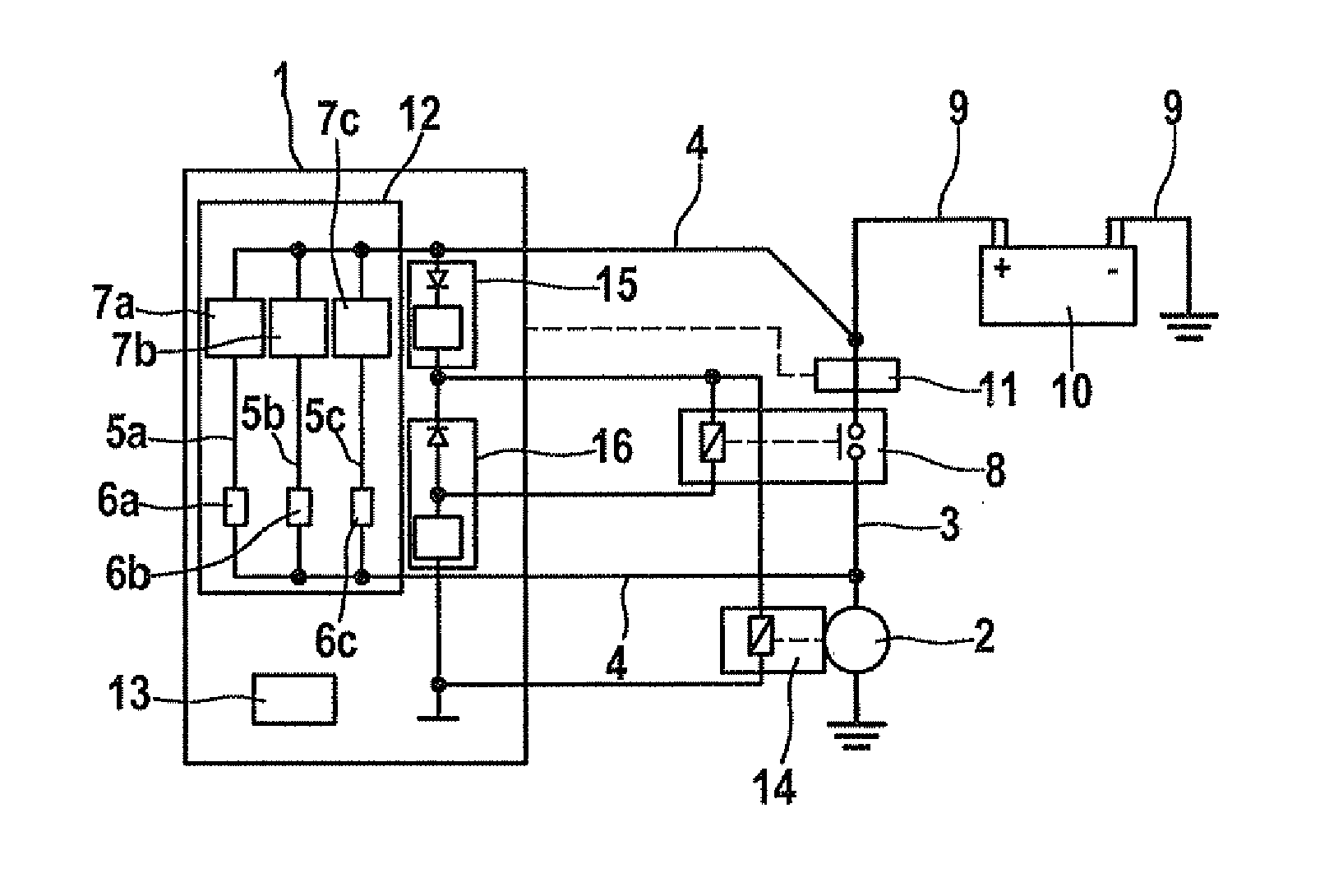
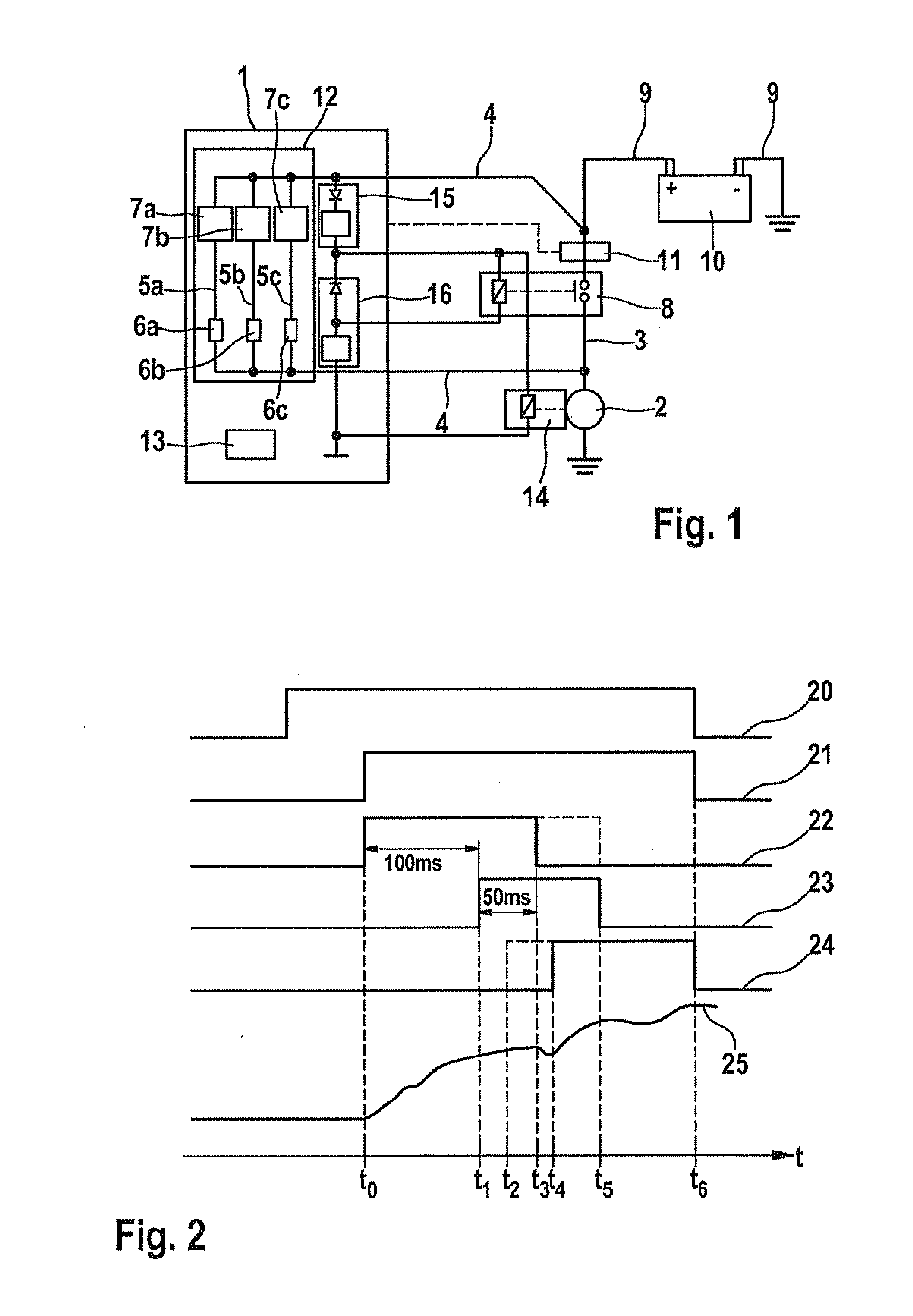
[0034]FIG. 1 shows a schematic circuit diagram of a control 1 for a starter device having a starter motor 2, a first current path, the so-called main current path 3, and an additional second current path, i.e., auxiliary current path 4, which is connected in parallel to main current path 3. Main and auxiliary current paths 3, 4 are each supplied from a battery 10 via a vehicle electrical system 9 and are designed for a redundant energization of starter motor 2.

[0035]Main current path 3 has an switching device 8 which is an integral part of a starter relay, which in addition includes a meshing device 14 having a relay coil for meshing a starter pinion (not shown) of starter motor 2 into an annular gear of an internal combustion engine (also not shown). Switching device 8 and meshing device 14 are thus implemented together in the starter relay, each having a coil winding, and are only shown separately in FIG. 1 to provide a better overview.

[0036]Auxiliary current path 4 passes through...


PUM


Abstract

A control is described for a starter device of an internal combustion engine in a vehicle having a starter motor, a first current path and at least one additional second current path, which is connected in parallel to the first current path, for energizing the starter motor, the first current path having an switching device, in particular a starter relay. In order to improve an energization of the starter motor, the control is in operative contact with a testing device for checking a switching state of the switching device and provided with an adapter for adapting the energization of the switching device.

Description

FIELD OF THE INVENTION[0001]The present invention relates to a control for a starter device of an internal combustion engine in a vehicle having a starter motor, a first current path and at least one additional second current path, which is connected in parallel to the first current path, for energizing the starter motor, the first current path having an switching device, in particular a starter relay.[0002]The present invention further relates to a method for operating a control, in particular of this type, for a starter device of an internal combustion engine in a vehicle having a starter motor, a first current path, which has an switching device, in particular a switching relay, and at least one additional second current path which is connected in parallel to the first current path, the starter motor being energized via the second current path, and the switching device being switched for energizing the starter motor via the first current path at a point in time t1. Finally, the p...

Claims


Application Information

Patent Timeline
Patent Type & Authority Applications(United States)
IPC IPC(8): F02N11/08
CPCF02N11/0814F02N11/0859F02N2250/02F02N2011/0874F02N2200/044F02N11/087
Inventor GE, JIEHERZOG, ACHIMSENGEBUSCH, FALCO
Owner ROBERT BOSCH GMBH
Learn More