Novel industrial dust collector device

An industrial dust collector and a new type of technology, applied in the direction of coupling device, two-part connection device, and parts of the connection device, can solve the problems of inconvenient dust removal operation, interruption of power supply, loose plug connection, etc. Effect

Inactive Publication Date: 2018-07-31
佛山金颖科技有限公司
View PDF1 Cites 0 Cited by
  • Summary
  • Abstract
  • Description
  • Claims
  • Application Information

AI Technical Summary

Problems solved by technology

[0002] Industrial dust collectors are widely used in industrial production. However, industrial dust collectors have relatively high power. In some factories, they are specially equipped with power distribution boxes for plugging and power supply of dust collectors. The mode is single, and the internal conductive sheet is set relatively outside. This conductive sheet is easily contacted by the metal sheet or metal rod. Therefore, when people who lack safety awareness insert the metal sheet or rod into the socket, it is easy to Electric shock accidents can easily cause casualties; at the same time, the dust collector needs to frequently move its position during the dust removal operation, and the dust collector only relies on the friction between the plug head and the plug seat to maintain the locked state when plugged in for power supply. It is easy to be affected by pulling the power supply line and cause loose plugging, resulting in interruption of power supply, which brings great inconvenience to the dust removal operation and needs to be improved.

Method used


Image

  • Novel industrial dust collector device
  • Novel industrial dust collector device
  • Novel industrial dust collector device

Examples


Embodiment Construction

[0025] All features disclosed in this specification, or steps in all methods or processes disclosed, may be combined in any manner, except for mutually exclusive features and / or steps.

[0026] Any feature disclosed in this specification (including any appended claims, abstract and drawings), unless expressly stated otherwise, may be replaced by alternative features which are equivalent or serve a similar purpose. That is, unless expressly stated otherwise, each feature is one example only of a series of equivalent or similar features.

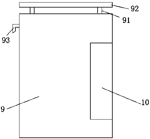
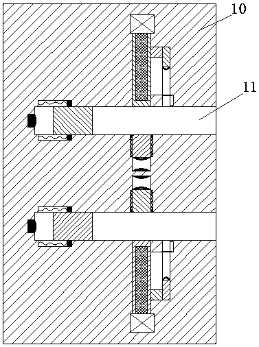
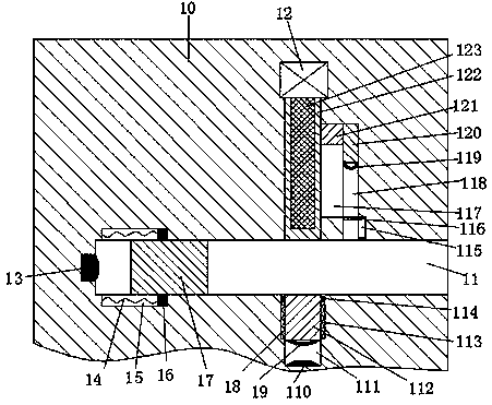
[0027] Such as Figure 1 to Figure 6As shown, a new type of industrial dust collector device of the device of the present invention includes a cabinet 9, a plug seat 10 arranged in the right side end face of the cabinet 9 and a plug head 20 connected with the dust collector, and the top end face of the cabinet 9 passes through The arm bar 91 is fixedly connected with a dustproof plate 92, and the front and rear sides of the left side of the c...


PUM


Abstract

The invention relates to a novel industrial dust collector device, which comprises a case, a plug pin seat arranged in the right end face of the case and a plug pin head connected with the dust collector, wherein the plug pin seat is internally provided with jacks with the opening facing towards the right in a vertically equivalent manner, the plug in seat is further provided with pushing slots with the opening facing towards the respective jacks in a vertically equivalent manner between the two jacks, each pushing slot is internally provided with a pushing arm in a sliding manner, the end wall, which is back to the corresponding jack, of each pushing slot is fixedly provided with a first power transmission terminal, the end face, which is back to the corresponding jack, of each pushing arm is fixedly provided with a power connecting piece, the end wall, which is back to the corresponding pushing slot, of each jack is internally provided with a first slide connecting slot which is opposite to the corresponding pushing slot, the opening of each first slide connecting slot faces towards the corresponding jack, the right end wall of each first slide connecting slot is provided with asecond slide connecting slot, the right end wall of each second slide connecting slot is internally provided with a third slide connecting slot communicated with the corresponding jack, each first slide connecting slot is internally provided with a first slide connecting block capable of sliding up and down, each second slide connecting slot is internally provided with a second slide connecting block capable of sliding up and down, and each third slide connecting slot is internally provided with a third slide connecting block capable of sliding up and down.

Description

technical field [0001] The invention relates to the technical field of industrial dust collectors, in particular to a novel industrial dust collector device. Background technique [0002] Industrial dust collectors are widely used in industrial production. However, industrial dust collectors have relatively high power. In some factories, they are specially equipped with power distribution boxes for plugging and power supply of dust collectors. The mode is single, and the internal conductive sheet is set relatively outside. This conductive sheet is easily contacted by the metal sheet or metal rod. Therefore, when people who lack safety awareness insert the metal sheet or rod into the socket, it is easy to Electric shock accidents can easily cause casualties; at the same time, the dust collector needs to frequently move its position during the dust removal operation, and the dust collector only relies on the friction between the plug head and the plug seat to maintain the lo...

Claims


Application Information

Patent Timeline
Patent Type & Authority Applications(China)
IPC IPC(8): H01R13/703H01R13/639H01R24/00
CPCH01R13/703H01R13/639H01R24/00
Inventor 廖广强
Owner 佛山金颖科技有限公司
Why Eureka
Try Eureka