Electric heating cleaning method and device

An electric heating and cleaning technology, applied in the direction of electrode cleaning, cleaning methods and appliances, pump components, etc., to achieve the effect of wide application range, compact structure and high environmental friendliness

Inactive Publication Date: 2010-06-30
赵钦基
4 Cites 12 Cited by

AI-Extracted Technical Summary

Problems solved by technology

It is also possible to set a non-stick coating on...

Abstract

The invention discloses an electric heating cleaning method. An electric heating functional component is made of an electric heating or conductive and magnetizing ferromagnetic material, or a functional component is provided with an electric heating part made of an electric heating or magnetizing ferromagnetic material to form the electric heating functional part; the functional component is a device the pollution of which can be eliminated by heating comprises a filter screen, a static purifying device electrode and a blade impeller. The dirt on the surface of the electric heating functional component is dehydrated, inactivated, melted, tendered, carbonized, burnt, shed and stripped by loading the current on the electric heating functional component. A non-stick coating is arranged on the surface of the electric heating functional component. An electric heating cleaning device produced by the method consists of an electric heating functional component and a heating power source. The electric heating cleaning device is characterized in that the electric heating functional component comprises a connecting interface which forms an electric circuit with the heating power source or comprises an electromagnetic coil for forming electromagnetic coupling with the electric heating functional component. The invention has the advantages of favorable cleaning effect, high speed, non-relation to mechanism movement, compact and reliable structure, wide application range, environment friendlessness and no raise dust or waste liquor discharge. Two embodiments are provided by combining with attached drawings.

Application Domain

Technology Topic

Image

  • Electric heating cleaning method and device
  • Electric heating cleaning method and device
  • Electric heating cleaning method and device

Examples

  • Experimental program(1)

Example Embodiment

[0012] Specific implementation method
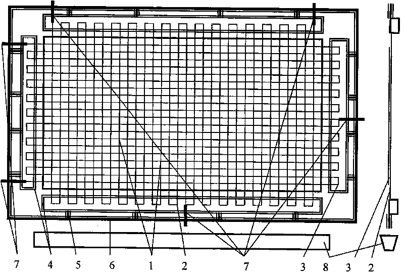
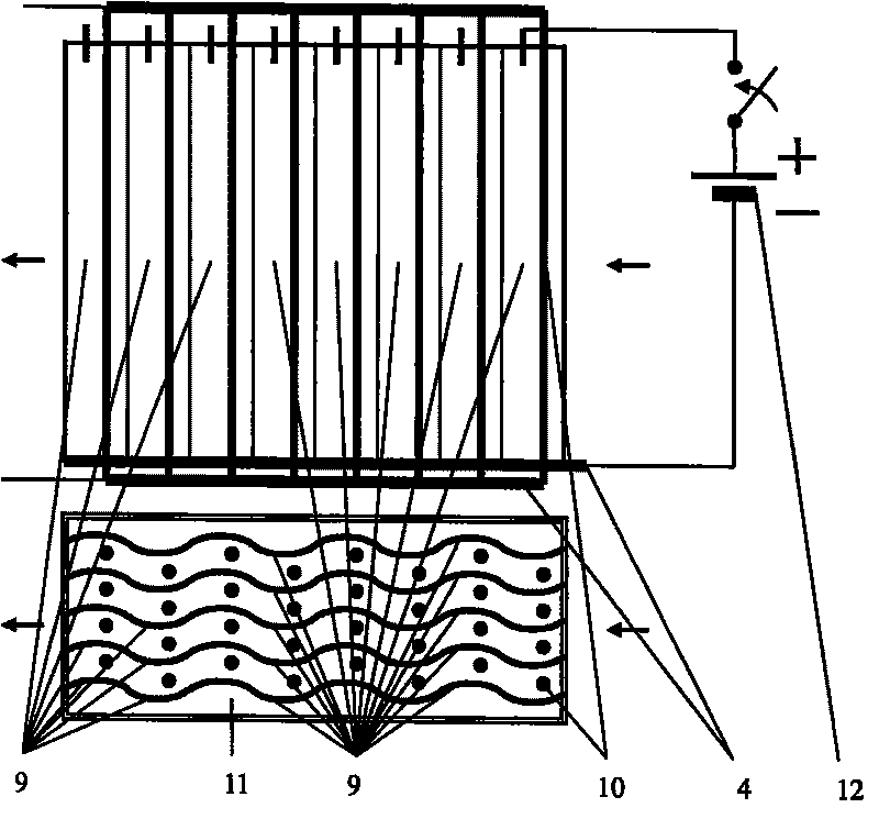
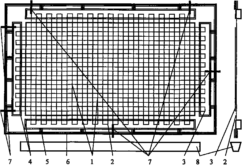
[0013] figure 1 In the embodiment, a non-cross-woven filter screen 2 composed of a layer of vertically arranged filamentous heating material 1 and a non-cross-woven filter screen 3 composed of a layer of horizontally arranged filamentous heating material 1 are close to each other to form an electric heating cleaning The filter device. The non-cross braided filter screen can be connected in series. The close arrangement of the non-cross-woven filter screens 2 and 3 can not only reduce the number of electrical branches and switching devices without short-circuit phenomenon, but also can obtain the filtering performance close to the warp-weft structure of the cross-woven filter screen. The filamentous electric heating materials 1 forming the non-cross-woven filter screens 2 and 3 are hung on an electrical connector 4 with an insulating base, and the electrical connector 4 is connected to the frame 6 through a spring 5. The spring 5 is used to absorb the end point displacement of the filamentary electric heating material 1 when it expands and contracts with heat and can avoid a short circuit accident caused by the relaxation of the filamentary electric heating material 1. The heating power source is electrically connected to the non-cross-woven filter screens 2 and 3 of the electrothermal function component through the connection interface lead 7 and the electrical connection piece 4. The connection interface also includes terminals and soldering tabs. The collection box 8 is used to collect the heating residue that is temporarily stored off. The odor generated during heating and cleaning can be absorbed by activated carbon or removed with a vacuum cleaner.
[0014] The heating power supply can use switching power supply, step-down transformer and eddy current transformer. A microprocessor can also be used to control and display the status of the electric heating cleaning process.
[0015] The heat generated by the current is proportional to the square of the resistance and the current. This means that for the same heating value, increasing the resistance value can reduce the current value. In many cases, it is easier to manufacture low-current power supplies. Therefore, the electric heating wire uses a resistivity of 0.1 ohm·mm 2 It is better for materials with stable physical and chemical properties under high temperature conditions.
[0016] The electric heating composite parts can be set on the functional parts in sheet, wire, mesh, paint and sintered electric heating or ferromagnetic materials, including carbon fiber composite materials; some stainless steel and most carbon steel are available For ferromagnet. For electric fan blades, a layer of heat-resistant insulating material can be coated on the iron blade, then a layer of electric heating paint and lead wires can be connected as the electrical connection interface. In this way, the blades of the electric fan can be cleaned with electric heating without wiping.
[0017] figure 2 In the embodiment, a plurality of sheet electrodes of the electrostatic cleaning dust removal device that can be independently connected to the heating power supply, and the electrode sheets 9 of the electrothermal function component unit are spliced ​​with each other to form a large corrugated curved surface electrode. Each unit electrode sheet 9 and the linear electrode 10 are electrically connected to the positive electrode and the negative electrode of the high voltage power supply, so that a strong and uniform electric field is established in almost the entire electrostatic cleaning and dust removal device 11. The oil fume or dust in the air enters the electric field and is adsorbed on the electrode sheets 9 and the linear electrodes 10 in a large amount. The electrostatic dust removal device can achieve an air purification rate of more than 90% in the best working state.
[0018] While purifying the air, a large amount of oil fume or dust will quickly accumulate on each unit electrode sheet 9 and the linear electrode 10, some of which will be oxidized into grease, stick to the electrode and reduce the effect of purifying and removing dust. The heating power supply 12 is connected to each unit electrode sheet 9 and the linear electrode 10 to form an electrical circuit through the connection interface electrical connector 4, so that the oil on each unit electrode sheet 9 and the linear electrode 10 can be heated and carbonized to achieve the purpose of cleaning. . Due to the large area of ​​the corrugated surface electrode, at the same time, the entire heating requires a large current. Therefore, using multiple unit electrode sheets 9 that can be independently powered on and heating them one by one can reduce the power of the power supply. From an electrical point of view, the splicing of the unit electrode sheets 9 should prevent the phenomenon of current bypass between each other.
[0019] In the same way, the use of multiple adjacent electric heating composite parts that can be independently connected to the heating power supply can also realize the electric heating cleaning of a large area with a low-power power supply.

PUM

no PUM

Description & Claims & Application Information

We can also present the details of the Description, Claims and Application information to help users get a comprehensive understanding of the technical details of the patent, such as background art, summary of invention, brief description of drawings, description of embodiments, and other original content. On the other hand, users can also determine the specific scope of protection of the technology through the list of claims; as well as understand the changes in the life cycle of the technology with the presentation of the patent timeline. Login to view more.

Similar technology patents

Surface cleaning equipment

ActiveCN103705179AReduce noiseGood cleaning effectFloor sweeping machinesScrub brushesEngineering
Owner:SUZHOU CHENGHE CLEANING EQUIP

Classification and recommendation of technical efficacy words

  • Good cleaning effect
  • Accelerate

Automatic duster

Owner:东莞市博思电子数码科技有限公司
Why Eureka
Try Eureka