Electric power control socket

A technology of power control and socket, which is applied in the direction of circuits, electrical components, coupling devices, etc., can solve the problems of potential safety hazards and the inability to limit children's use, and achieve the effect of improving the safety of electricity use and the safety factor of electricity use

Inactive Publication Date: 2010-10-20
SHINING UNION
View PDF4 Cites 13 Cited by
  • Summary
  • Abstract
  • Description
  • Claims
  • Application Information

AI Technical Summary

Problems solved by technology

[0013] In view of the above-mentioned defects, the purpose of the present invention is to provide a power control socket to solve the problems of potential safety hazards and the inability to restrict children from using certain electrical appliances in the traditional technology.

Method used


Image

  • Electric power control socket
  • Electric power control socket
  • Electric power control socket

Examples


Embodiment 1

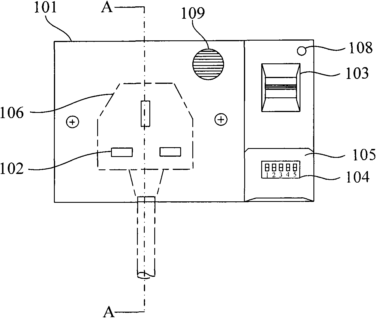
[0030] Such as figure 1 Shown is a front view of a power control socket provided in Embodiment 1 of the present invention. The surface of the power control socket includes a housing 101, a socket hole 102, a fingerprint scanning part 103, a dial switch group 104, a sealing cover 105, and an LED indicator light 108 and loudspeaker 109, socket hole 102, fingerprint scanning part 103, dial switch group 104, LED indicator light 108 and loudspeaker 109 are all arranged on the shell 101, wherein dial switch group 104, sealing cover 105, LED indicator light 108 and speaker 109 are optional.

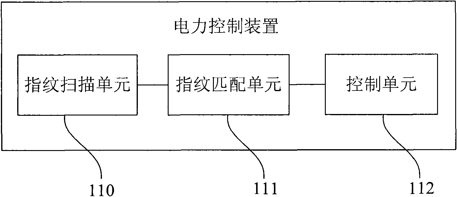
[0031] The above is only a surface structure diagram of a power control socket according to the embodiment of the present invention, which also includes a power control device, which includes a fingerprint scanning unit 110, a fingerprint matching unit 111 and a control unit 112 (see figure 2 ), and the fingerprint scanning unit 110, the fingerprint matching unit 111 and the control unit 112 a...

Embodiment 2

[0045] Such as Figure 6 Shown is a schematic structural diagram of a power control device provided by Embodiment 2 of the present invention. The power control device 600 includes a fingerprint scanning unit 610, a fingerprint matching unit 620 and a control unit 630, which can complete the basic functions of fingerprint scanning, matching and controlling power supply. repeat.

[0046] In addition, if Figure 6 As shown, in this embodiment, the power control device 600 also includes an emergency switch unit 640, which is connected to the socket 700, and is used for when the fingerprint scanning unit 610, the fingerprint matching unit 620 or the control unit 630 fails. , when the power control device 600 cannot control the power, the emergency switch unit 640 is manually toggled to control the power supply, and its function is equivalent to a failure emergency system. The emergency switch unit 640 can be composed of a number of DIP switches. Here, a DIP switch group consisti...


PUM


Abstract

The invention provides an electric power control socket, comprising socket holes, a shell, an electric power control device and a microswitch. The electric power control device comprises a fingerprint scanning unit, a fingerprint matching unit and a controlling unit. The scanning part of the fingerprint scanning unit is arranged on the shell, and the fingerprint scanning unit, the fingerprint matching unit and the controlling unit are connected in sequence. The microswitch is arranged at the back of the socket holes, and is used for processing circuit when a plug is inserted into the socket holes, thereby realizing the control for the electric power through the controlling unit according to the matching result of the finger print. The electric power control socket of the embodiment of the invention controls the electric power of the socket through the fingerprint authentication and the microswitch, and greatly improves the security of electric power utilization without the worry of electric shock accident caused by the playing of the socket of the kids.

Description

[0001] This application claims the priority of the Hong Kong short-term patent application with application number 09103586.5 and titled "An Electric Power Control Device" filed on April 17, 2009, the entire contents of which are hereby incorporated by reference. technical field [0002] The invention relates to the field of electrical control, in particular to a power control socket controlled by fingerprint authentication. Background technique [0003] Nowadays, there are a large number of household appliances and power sockets in houses, and the safety of using electricity has received widespread attention. Most of our household appliances use 220V AC, which is an unsafe voltage. In addition, some household appliances, such as televisions, generate high voltages of more than 10,000 V. Once the human body is exposed to such a high voltage, electric shock will occur. It is life-threatening; the socket directly provides 220V alternating current. [0004] Traditional househo...

Claims


Application Information

Patent Timeline
Patent Type & Authority Applications(China)
IPC IPC(8): H01R13/66H01R13/70G06K9/00
CPCG07C9/00158H01R24/76H01R2103/00H01R13/7036G07C9/00896G07C9/37H01R13/70H01R13/6683H01R13/7038H01R25/006
Inventor 王国芳程佩仪
Owner SHINING UNION
Why Eureka
Try Eureka