Transformer structure and manufacturing method thereof

A manufacturing method and technology of transformers, applied in transformers, fixed transformers, transformer/inductor casings, etc., can solve problems such as insulation failure, increased manufacturing process, and defective tape quality

Active Publication Date: 2011-05-25
DELTA ELECTRONICS INC
View PDF0 Cites 11 Cited by
  • Summary
  • Abstract
  • Description
  • Claims
  • Application Information

AI Technical Summary

Problems solved by technology

In order to achieve effective isolation, it is common in practice that, in addition to the increase in the complexity of the process such as the application of adhesive tape, or incorrect application, or the quality of the adhesive tap

Method used


Image

  • Transformer structure and manufacturing method thereof
  • Transformer structure and manufacturing method thereof
  • Transformer structure and manufacturing method thereof

Examples


Embodiment Construction

[0046] In the description in the following paragraphs, several typical embodiments sufficient to embody the features and advantages of the present invention will be described in detail. It is stated in advance that the present invention can also have various changes in different implementation forms, but none of them depart from the scope of the present invention, so the following descriptions and drawings are essentially only used to illustrate some embodiments of the present invention, not used to limit the invention.

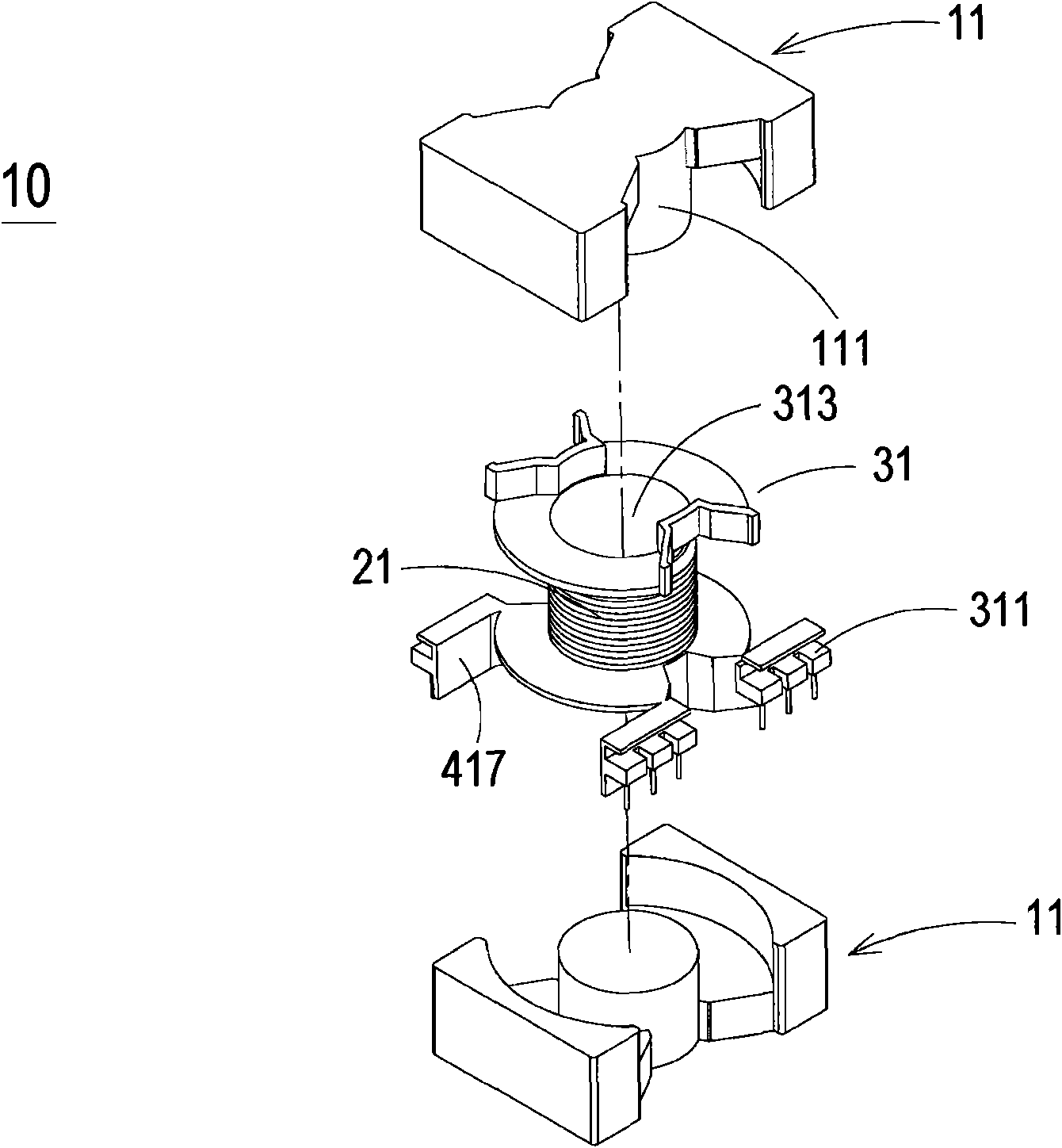
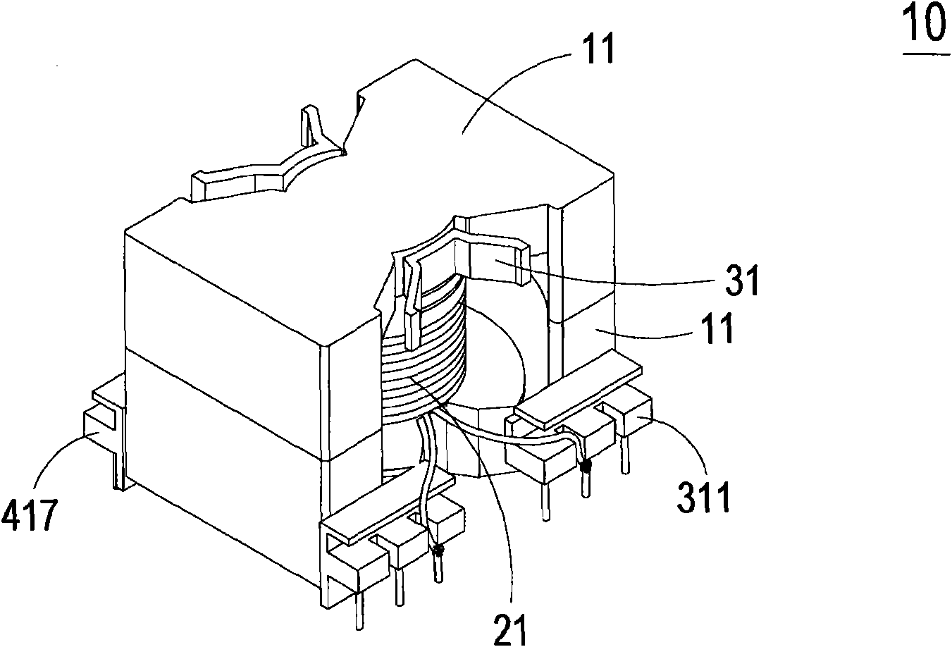
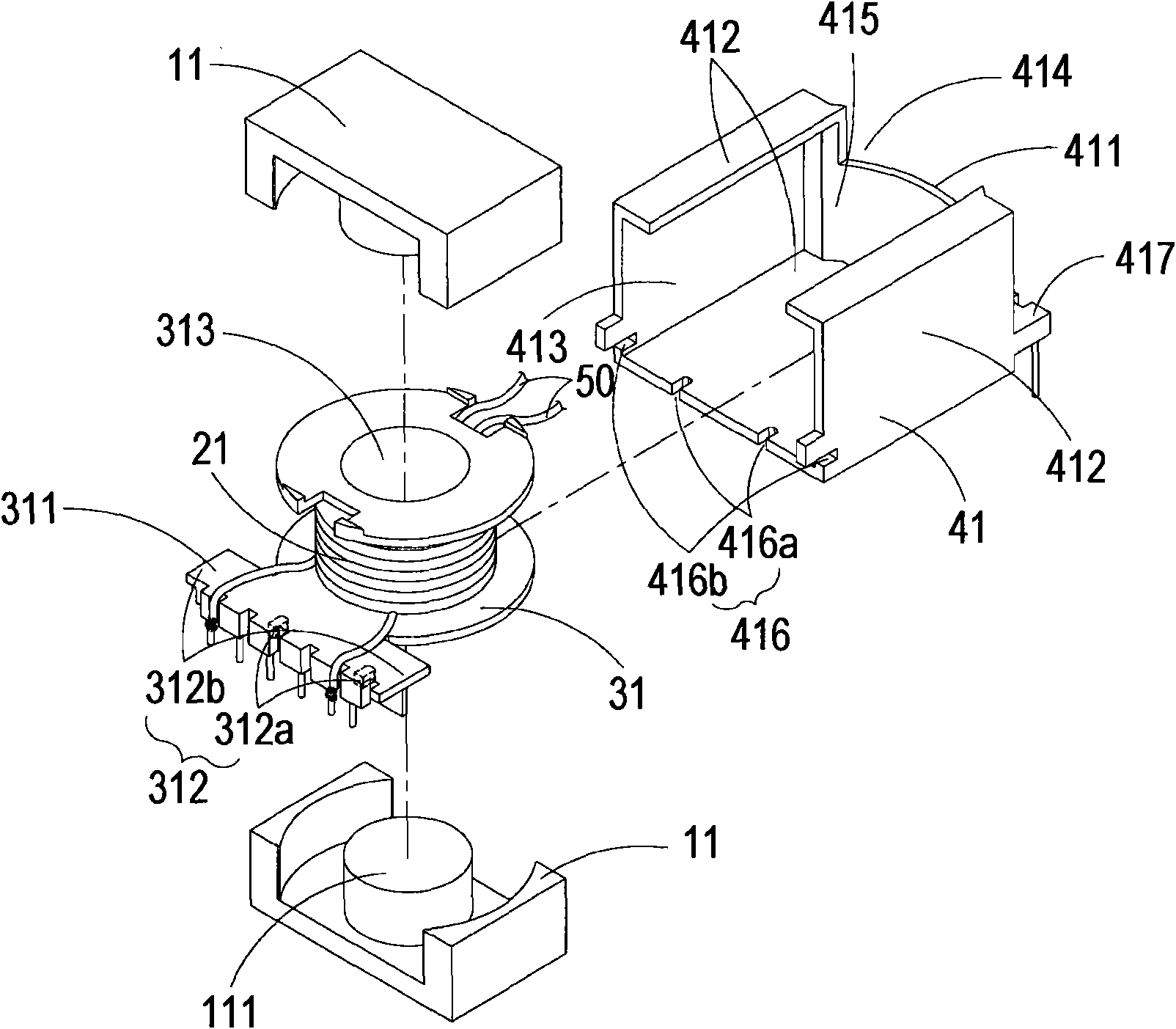
[0047] see image 3, which is an exploded schematic diagram of a transformer structure in a preferred embodiment of the present invention. That is, as illustrated in this embodiment, the transformer structure includes a magnetic core 11 , a coil winding 21 , a coil bobbin 31 and an insulating cover 41 . The coil winding 21 includes a primary side coil (not shown) and a secondary side coil (not shown), which are arranged on the coil bobbin 31 and combined wi...


PUM


Abstract

The invention relates to a transformer structure and a manufacturing method thereof. The transformer structure at least comprises a magnetic core, a coil winding, a coil reel and an insulation casing cover. The coil winding is provided with a primary side coil and a secondary side coil which wind on the coil reel and are integrated with the magnetic core, wherein a primary side input connection end and a reel clamping part are arranged on the coil reel. The insulation casing cover is provided with a first opening which is used for holding the magnetic core, the coil winding and the coil reel,a first sidewall which has a second opening for facilitating the output of the winding, a second sidewall which has a casing cover clamping part which is clamped with the reel clamping part, and a primary side output connection end and a secondary side output connection end. Therefore, the magnetic core of the transformer is effectively isolated from other elements so as to ensure electrical safety.

Description

technical field [0001] The invention relates to a transformer structure and a manufacturing method thereof, in particular to a transformer structure and a manufacturing method thereof which can effectively improve the electrical safety of the transformer with regard to magnetic core insulation. Background technique [0002] Transformers are widely used in various electronic devices, and are indispensable components for various power supply devices in transmitting and processing power. In order to meet the latest demands of the market, it is an inevitable design direction that the components of the electronic device are densely packed due to thinness, lightness, shortness and continuous improvement of the efficacy of the electronic device. How to reduce the size of the transformer to meet the above design trend has become an important issue in transformer design. [0003] see figure 1 and figure 2 , which shows a schematic diagram of decomposition and assembly of a tradit...

Claims


Application Information

Patent Timeline
IPC IPC(8): H01F30/06H01F27/30H01F27/24H01F27/02H01F27/29
Inventor 廖高材钟熙国彭明贤洪楀量
Owner DELTA ELECTRONICS INC
Why Eureka
Try Eureka