Unlock instant, AI-driven research and patent intelligence for your innovation.

Electromagnetic transducer

Active Publication Date: 2012-07-12
AAC ACOUSTIC TECH (SHENZHEN) CO LTD +1
View PDF3 Cites 13 Cited by
  • Summary
  • Abstract
  • Description
  • Claims
  • Application Information

AI Technical Summary

Problems solved by technology

However, the above mentioned elastic plate typically enable generating deformation only along one direction, which limits the vibrating amplitude of the vibrating unit, and leads to damage of inner components of the vibrator during falling off.

Method used


Image

  • Electromagnetic transducer
  • Electromagnetic transducer
  • Electromagnetic transducer

Examples


Embodiment Construction

[0008]Reference will now be made to describe the exemplary embodiment of the present invention in detail.

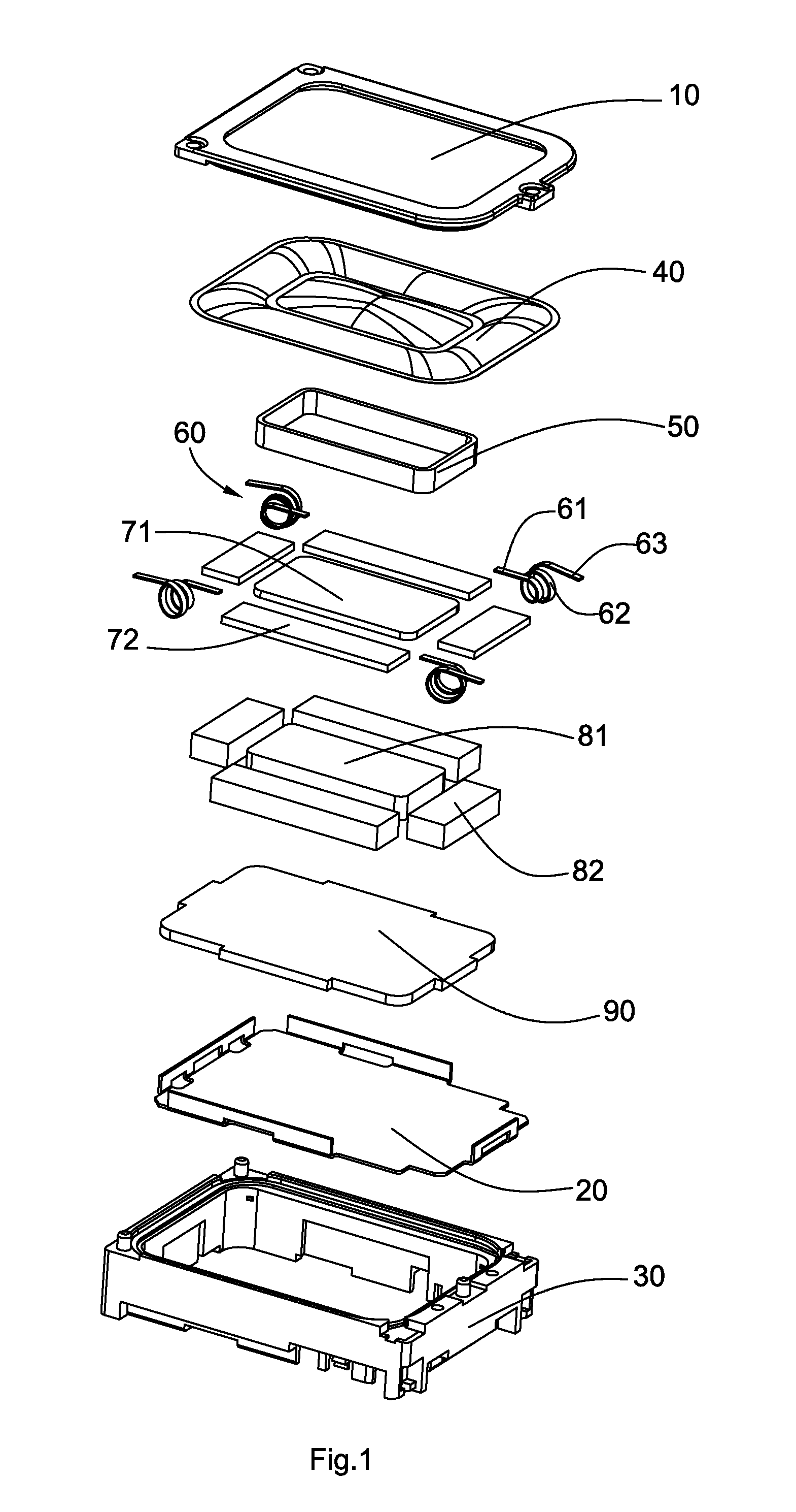
[0009]Referring to FIGS. 1 and 2, a multifunctional electromagnetic transducer comprises a bracket 30 forming an inner face, a lower cover 20 assembled with the bracket 30, a magnetic circuit part suspended in the bracket 30, an assistant part assembled to the bracket 30 for suspending the magnetic circuit part in the bracket 30, an voice generating part actuated by the magnetic circuit part, and an upper cover 10 protecting the voice generating part. The voice generating part comprises a diaphragm 40 supported by the bracket 30, and a voice coil 50 connected directly or indirectly with a lower surface of the diaphragm 40 and actuated by the magnetic field of the magnetic circuit part. The upper cover 10 is joined with the periphery of the diaphragm 40. The multifunctional electromagnetic transducer enables generating both sound and vibration.

[0010]Referring especially to FIG. 2,...


PUM


Abstract

A multifunctional electromagnetic transducer includes a bracket, a vibrating unit including a magnetic circuit part receiving in the bracket, and a plurality of helical wound springs assembled to the bracket for sustaining the magnetic circuit part. The magnetic circuit part defines a pole plate, a first magnet disposed at a center portion of the pole plate, and a plurality of second magnets surrounding the first magnet and forming a magnetic gap corporately with the first magnet. Each of the second magnets forms a receiving gap corporately with an adjacent second magnet. A voice coil is partially inserted into the magnetic gap.

Description

FIELD OF THE INVENTION[0001]The present disclosure relates to transducers to be mounted in terminal equipments for converting electrical signals to audible sounds, and more particularly to an electromagnetic transducer.DESCRIPTION OF RELATED ART[0002]With the rapid development of the portable devices such as cellular phones, people request for more and more functions. In the field of music enjoying of the cellular phone, a multifunction device enabling providing both audible and tactile sensations for amusement has already been widely used, which boosts the quick development of multifunctional devices.[0003]An electromagnetic transducer related to the present invention comprises a bracket, a magnetic circuit part received in the bracket, and an assistant part connecting to the bracket. The magnetic circuit part includes a single magnet and a single magnetic frame corporately forming a magnetic circuit. The magnetic frame is assembled with the assistant part so that the magnetic circ...

Claims


Application Information

Patent Timeline
IPC IPC(8): H04R1/00
CPCH04R9/025H04R11/02H04R1/025H04R9/06
Inventor LI, LIN-ZHENWEI, SUO-HE
Owner AAC ACOUSTIC TECH (SHENZHEN) CO LTD