Fixing Device And Method, And Image Forming Apparatus Incorporating Same

a technology of fixing device and fixing method, which is applied in the direction of electrographic process apparatus, instruments, optics, etc., can solve the problems of defective fusing and the discontinuous nature of one of the power-turn-on duties

Inactive Publication Date: 2012-07-12
RICOH KK
View PDF13 Cites 72 Cited by
  • Summary
  • Abstract
  • Description
  • Claims
  • Application Information

AI Technical Summary

Benefits of technology

[0016]In yet another aspect, there is provided a method of controlling the temperature of a fixing device comprising the steps of supplying electric power to the heater included in the fixing device by turning on/off electricity suppli

Problems solved by technology

However, supplying a heater with power using soft-start control while gradually increasing a phase angle means that, near duties of 0% and 100%, one of the power

Method used


Image

  • Fixing Device And Method, And Image Forming Apparatus Incorporating Same
  • Fixing Device And Method, And Image Forming Apparatus Incorporating Same
  • Fixing Device And Method, And Image Forming Apparatus Incorporating Same

Examples


Embodiment Construction

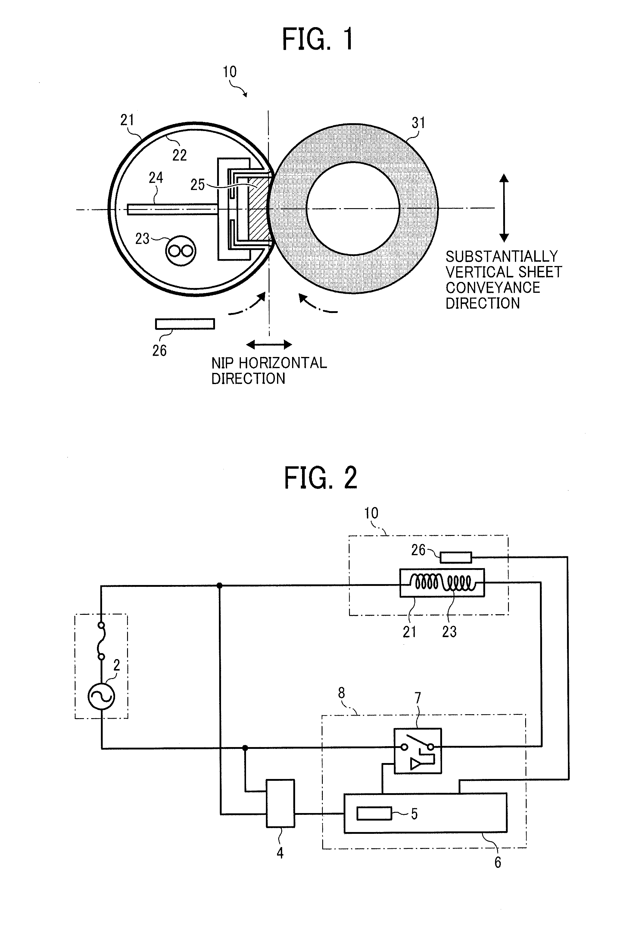
[0024]Referring now to the drawings, wherein like reference numerals designate identical or corresponding parts throughout the several views thereof and in particular to FIG. 1, a cross-sectional diagram shows the main parts of a fixing device according to various embodiments of the present invention.

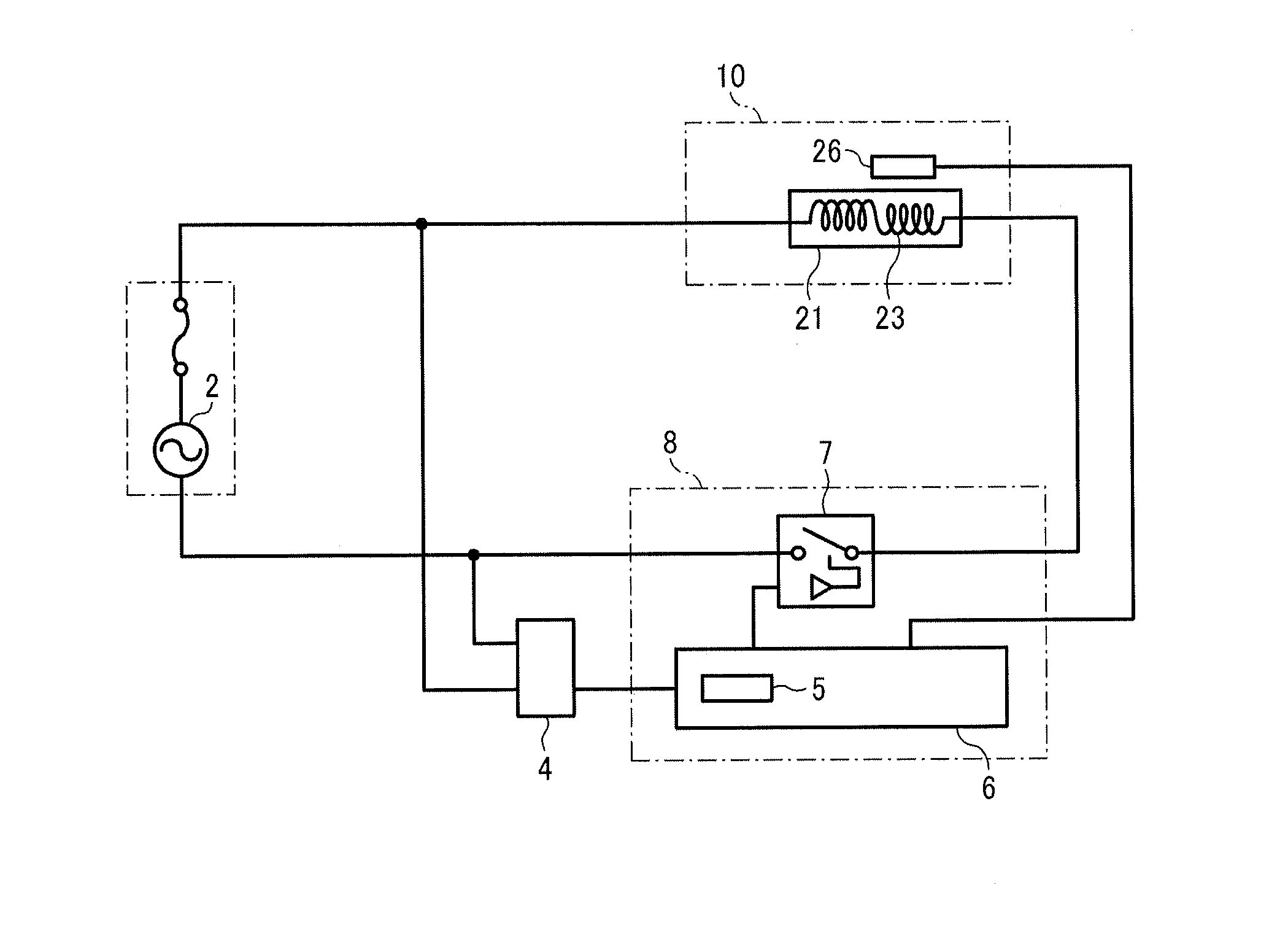
[0025]Specifically, a fixing unit 10 in this figure includes a fixing belt 21, a metal pipe 22 arranged close to an inner circumferential surface of the fixing belt 21, and around which the fixing belt 21 rotates, a heater 23, and a pressure rotor 31 (in this example, a pressing roller) or the like in a fixing device housing, which is not illustrated. In the present embodiment, the heater 23 is a Halogen heater that heats the fixing belt 21 through the metal pipe 22. A temperature detector 26 is arranged near the fixing device 21.

[0026]Also held by a supporter 24 (in this example, a metal pipe) inside of a loop of the fixing device 21 is a nip formation member 25 in direct sliding conta...


PUM


Abstract

A fixing device includes a heater to generate heat based on soft-start control. The heater is supplied with power using different power-turn-on-duty control patterns in accordance with power requirements and an operation mode of the fixing device.

Description

CROSS-REFERENCE TO RELATED APPLICATION[0001]This patent application is based on and claims priority pursuant to 35 U.S.C. §119 to Japanese Patent Application No. 2011-001841, filed on Jan. 7, 2011 in the Japanese Patent Office, the entire disclosure of which is hereby incorporated by reference herein.FIELD OF THE INVENTION[0002]The present invention relates to a fixing device and system and an image formation apparatus.BACKGROUND OF THE INVENTION[0003]Image formation apparatuses using electrophotography, such as photocopiers, printers, fax machines, etc., are well known, as disclosed for example in Japanese Patent Application Publication Nos. H10-74023 (JP-H10-74023-A) and H11-52783(JP-H11-52783-A).[0004]To form images, such conventional apparatuses first form an electrostatic latent image on a surface of a photosensitive drum of an image bearer. The latent image is then developed into a visible image using toner as a development agent. The thus-developed image is transferred onto a...

Claims


Application Information

Patent Timeline
IPC IPC(8): G03G13/20G03G15/20
CPCG03G15/205
Inventor IKEBUCHI, YUTAKAYOSHIKAWA, MASAAKIISHII, KENJIARAI, YUJITAKAGI, HIROMASAIWAYA, NAOKITOKUDA, TETSUOYAMAGUCHI, YOSHIKISESHITA, TAKUYAIMADA, TAKAHIROFUJIMOTO, IPPEIYOSHINAGA, HIROSHIGOTOH, HAJIMEYOSHIURA, ARINOBUSHIMOKAWA, TOSHIHIKO
Owner RICOH KK
Why Eureka
Try Eureka