Forward Mounted Gun Sight with Illumination Apparatus

Active Publication Date: 2012-07-19
MAGPUL INDUSTRIES
View PDF27 Cites 23 Cited by
  • Summary
  • Abstract
  • Description
  • Claims
  • Application Information

AI Technical Summary

Benefits of technology

[0006]In view of the foregoing disadvantages inherent in the known types of illumination devices, this invention provides a combined back-up sight and illumination apparatus. As such, the present invention's general purpose is to provide a new and improved back-up

Problems solved by technology

This position, however block som

Method used


Image

  • Forward Mounted Gun Sight with Illumination Apparatus
  • Forward Mounted Gun Sight with Illumination Apparatus
  • Forward Mounted Gun Sight with Illumination Apparatus

Examples


Embodiment Construction

[0018]With reference now to the drawings, the preferred embodiment of the front back-up sight is herein described. It should be noted that the articles “a”, “an”, and “the”, as used in this specification, include plural referents unless the content clearly dictates otherwise.

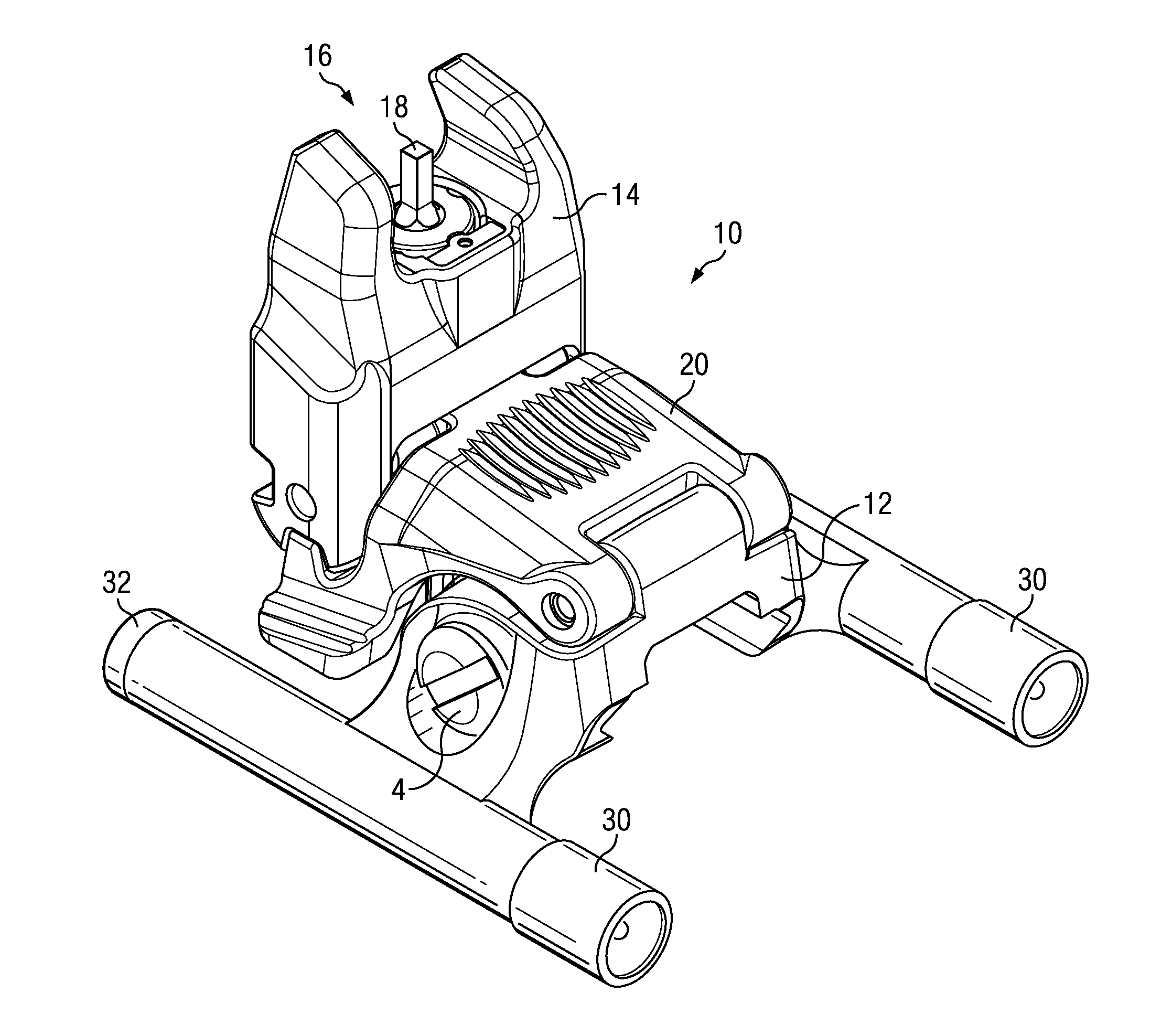
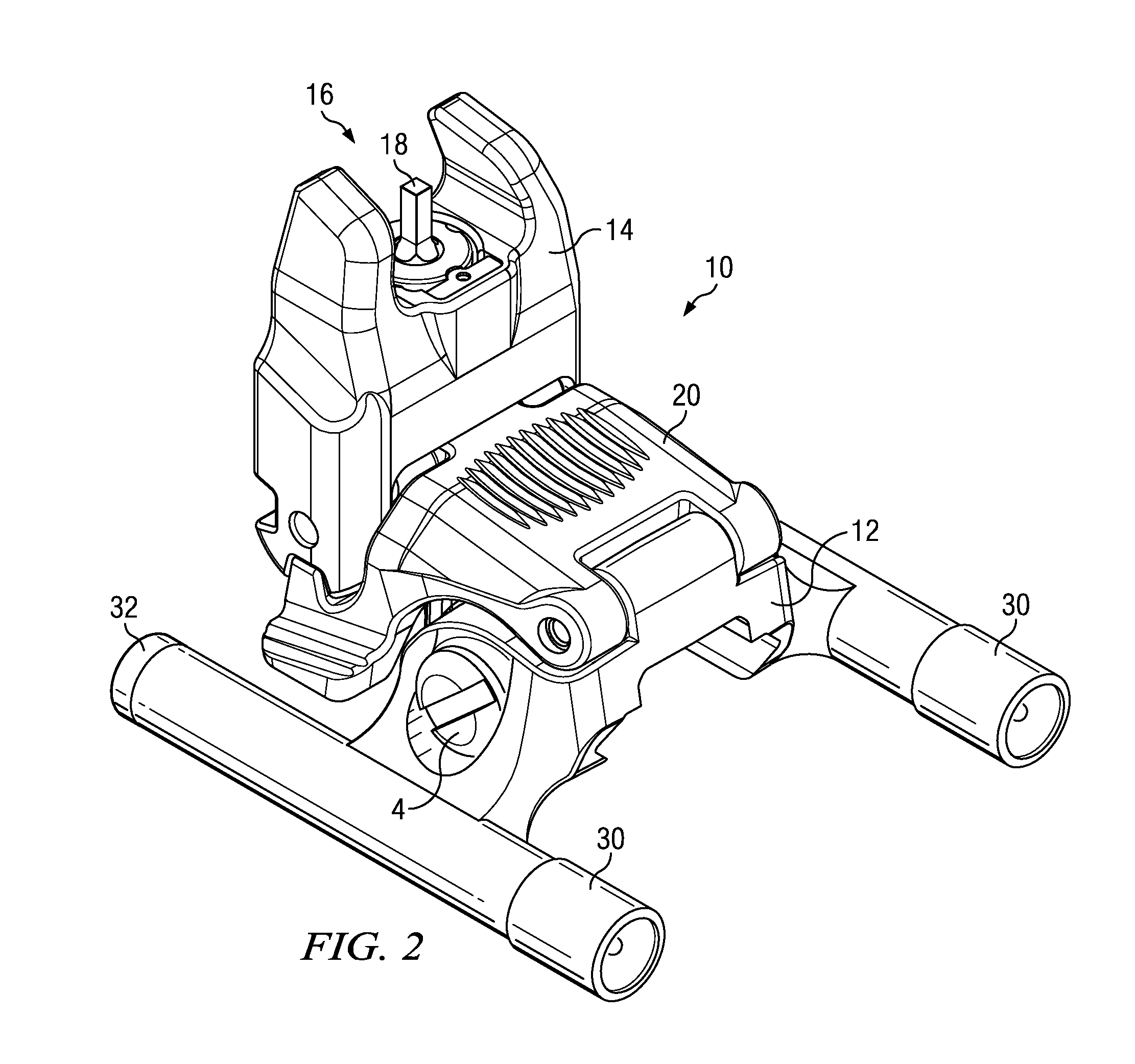
[0019]With reference to FIGS. 3-6, the back-up sight 10 comprises a base 12 and sight housing 14 hingedly connected together. The sight housing is spring-biased 22 (FIG. 6) in the deployed position, as shown in FIG. 4. A latch 20 is also hingedly attached to the base 12. In the depicted embodiment, the latch 20 forms a carapace over base 12 and is hinged at an edge of the base 12 opposite the sight housing 14. Latch 20 features two teeth 24, on opposite sides, and each tooth 24 selectively engages one of a set of two notches 26, 28, each set likewise being on opposite sides of the sight housing 14. While stowed, FIG. 5, latch 20 engages notches 26 and secures the sight housing 14 against the spring bias 22. Upon...


PUM


Abstract

The present invention is a rail mounted back-up sight with at least one, but preferred two, illumination apparatuses mounted thereon. The back-up sight features a sight housing that is configured to selectively alternate between a stowed and a spring-biased deployed position. Any type of illumination apparatus may be used, but the preferred apparatus is a flashlight, mounted upon wither side of a sight base. Either a front or a rear sight may be utilized as could different types of illumination apparatuses.

Description

CROSS-REFERENCES TO RELATED APPLICATIONS[0001]This Application claims priority as a non-provisional perfection of prior provisional application No. 61 / 286,365, filed Dec. 14, 2009, and incorporates the same by reference herein.FIELD OF THE INVENTION[0002]The present invention relates to the field of firearms and more particularly relates to a forward back-up sight with an illumination apparatus mounted thereon.BACKGROUND OF THE INVENTION[0003]The firearm is the weapon of choice in most modern militaries. It is a tool used in many different battle and practice scenarios, including low-light situations. However, in order to effectively use a firearm, one must be able to see a target. To this end, many methods and systems have been developed to mount a light or a targeting device on a firearm in a manner to keep the users hands otherwise free to operate the weapon. These solutions have endeavored to position the light in a manner to illuminate what is in front of the shooter, but must ...

Claims


Application Information

Patent Timeline
IPC IPC(8): F41G1/35
CPCF41G1/02F41G1/18F41G11/003F41G1/36F41G1/35
Inventor HALEY, TRAVIS D.BURT, ERIC C.FITZPATRICK, RICHARD M.MAYBERY, MICHAEL T.
Owner MAGPUL INDUSTRIES
Why Eureka
Try Eureka