Massage shower that can achieve the dynamic switch of the water flow

a shower and water flow technology, applied in the field of massage showers, can solve problems such as affecting the massage effect, and achieve the effect of excellent massag

Inactive Publication Date: 2012-07-19
XIAMEN SOLEX HIGH TECH IND CO LTD
View PDF2 Cites 12 Cited by
  • Summary
  • Abstract
  • Description
  • Claims
  • Application Information

AI Technical Summary

Benefits of technology

[0003]The object of the present invention is to overcome the defects at the prior art and offer a massage shower that can achieve the dynamic switch of the water flow. The said massage shower can achieve the dynamic switch of different effluent holes on the face cover of the shower during the using process, and achieve excellent massage effect.
[0023]As known from the said description, the present invention creatively offer a simple structural massage shower that can achieve the dynamic switch of the water flow, and the said impeller and the said moving plate are connected through a differential gearing transmission retarding mechanism in the said massage shower, the water drives the moving plate of the water-division unit to rotate after its speed is reduced by the retarding mechanism, at the moment, the rotating frequency of the moving plate is reduced, and the dynamic switch of different effluent holes on the face cover would be lower, and make the user feel it, achieving excellent massage effect.

Problems solved by technology

However, the said massage shower just achieve the change of the massage head's action, it cannot control the dynamic water outlet of different massage head; and because the said massage shower does not have retarding mechanism, the usually big water pressure and flow rate make the rotation speed of the impeller fast, so that the rotation frequency of the massage disk driven by the impeller is too fast and it affects the massage effect.

Method used


Image

  • Massage shower that can achieve the dynamic switch of the water flow
  • Massage shower that can achieve the dynamic switch of the water flow
  • Massage shower that can achieve the dynamic switch of the water flow

Examples


embodiment 1

[0035]With the following description of the drawings and specific embodiments, the invention shall be further described in details.

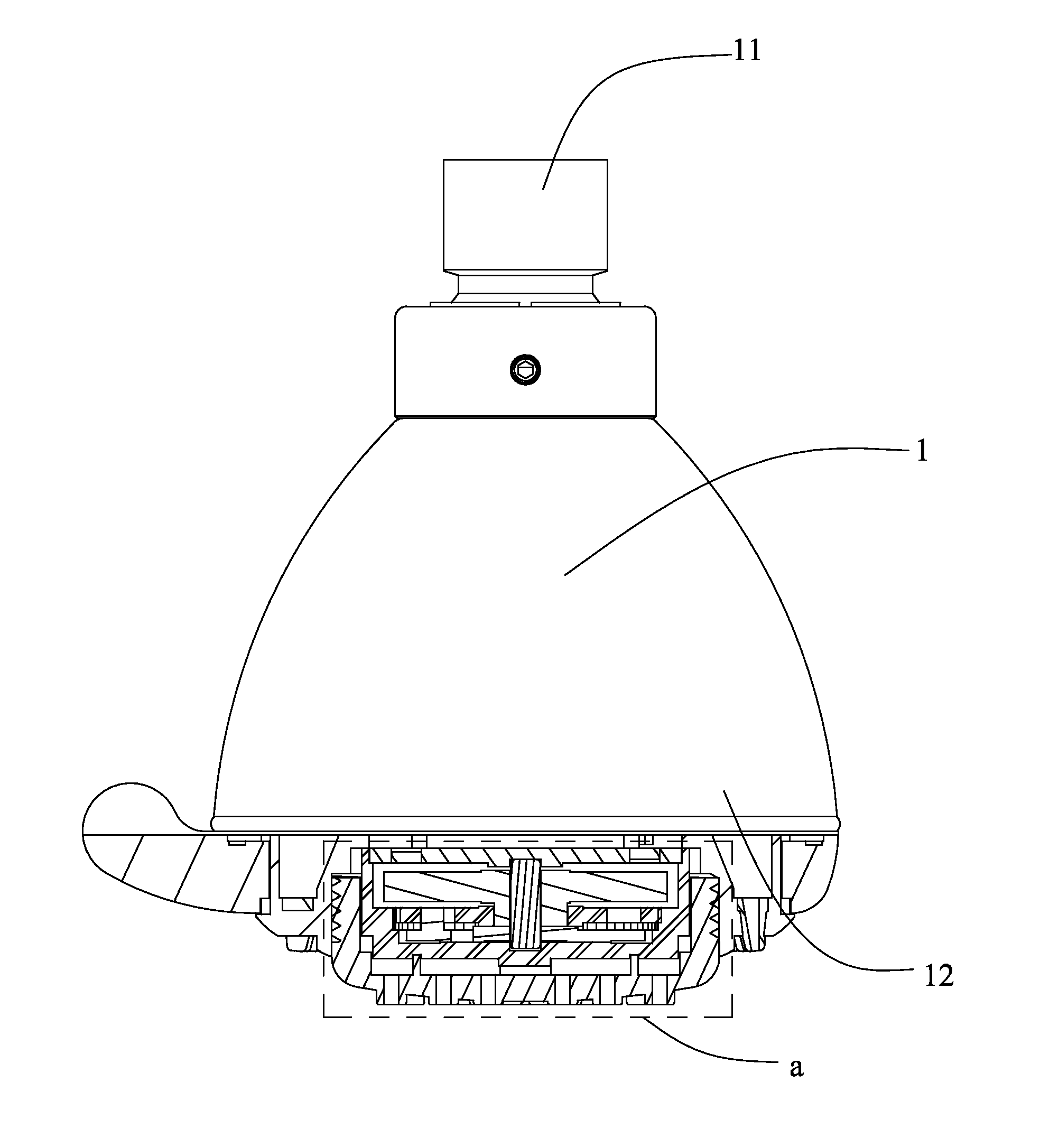
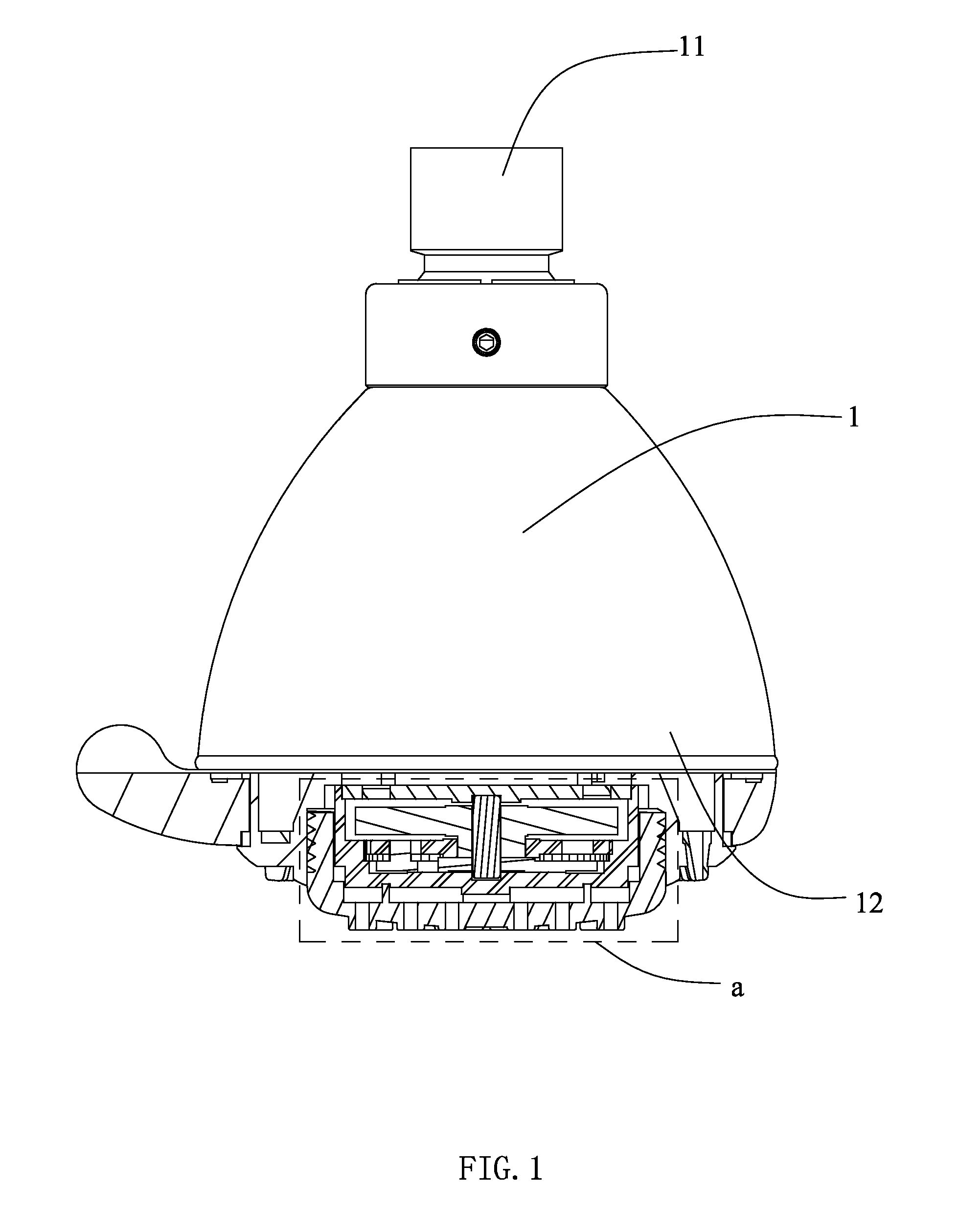
[0036]As shown in FIG. 1, FIG. 2, FIG. 3, FIG. 4 and FIG. 5, the massage shower that can achieve the dynamic switch of the water flow comprises a hollow essential body 1 which has an entry end 11 and an effluent end 12.

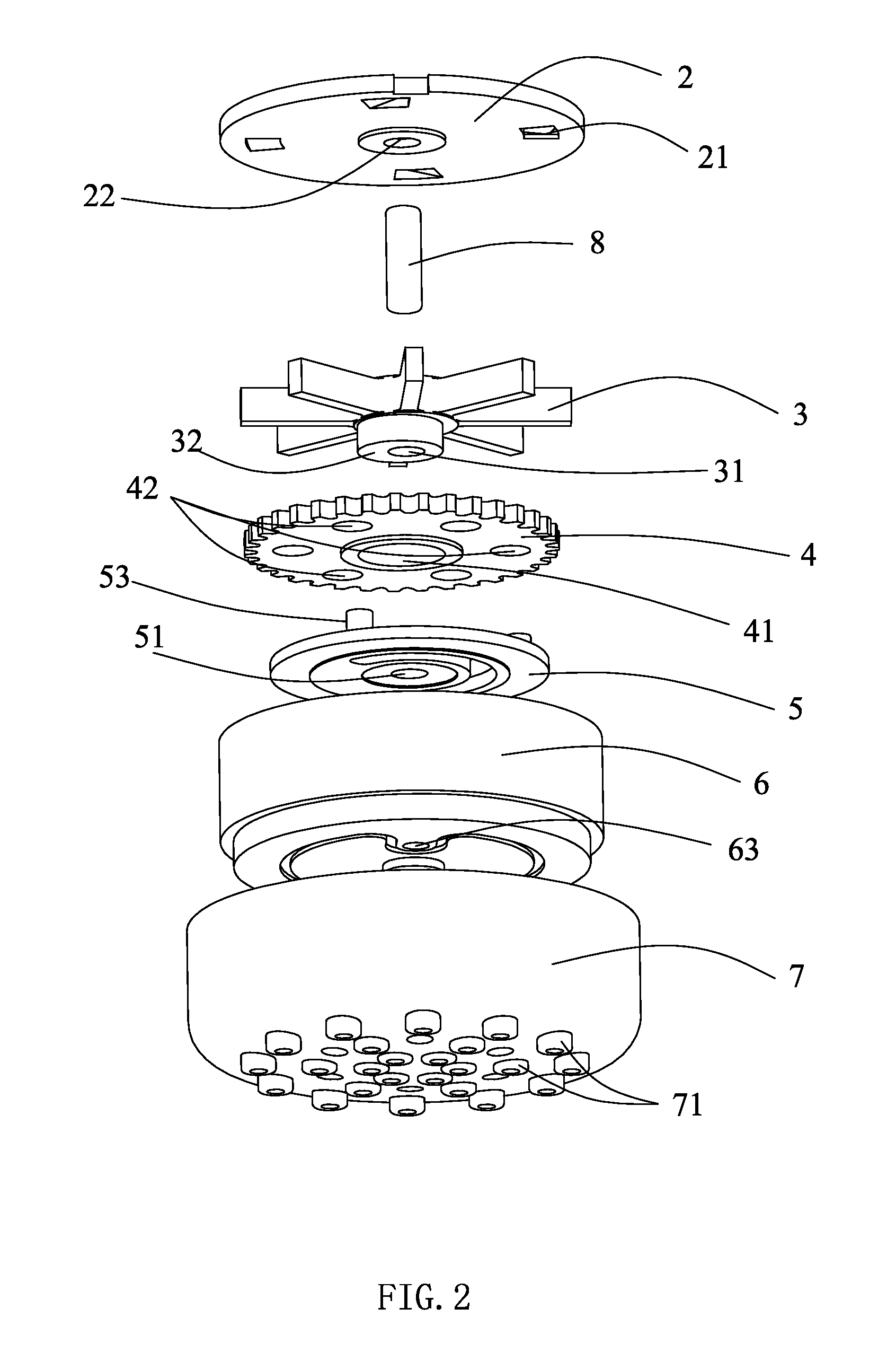
[0037]An oblique water body 2 is fixed at the effluent end 12 of the essential body1, in which several oblique holes 21 that form oblique water flow are distributed, and of which the bottom surface has an upper shaft base 22.

[0038]An impeller 3 that has a center hole 31 is set under the oblique water body 1, the oblique water flow from the oblique hole 21 impacts the blades of the impeller 3 and drives the impeller 3 to rotate; the periphery of the center hole 31 extends downwards to form a eccentric wheel 32.

[0039]An external gear 4 that has a center hole 41 is set under the impeller 3, and the external gear 4 is sleeved around the outboa...


PUM


Abstract

The present invention discloses a massage shower that can achieve the dynamic switch of the water flow, it comprises a hollow essential body, a oblique water body, a impeller that is under the said oblique water body, a face cover component that has the effluent holes and a moving plate used to switch the effluent holes of different areas in the face cover component, the said impeller and the said moving plate are connected through a differential gearing transmission retarding mechanism. The said massage shower can achieve the dynamic switch of different effluent holes on the face cover of the shower during the using process, and achieve excellent massage effect.

Description

FIELD OF THE INVENTION[0001]The present invention relates to a massage shower, more particularly to a massage shower that can achieve the dynamic switch of the water flow.BACKGROUND OF THE INVENTION[0002]To get good massage effect, the massage shower is not only needed to form pressure water column, but also need to achieve the dynamic switch of the pressure water column. Thereby, CN101020165A discloses a massage shower that can achieve the dynamic switch of the pressure water column, it at least comprises a essential body, a oblique water body, a impeller, a massage dish and a face cover, the essential body has a grip, a water inlet and a water outlet, the oblique water body, the impeller, the massage dish and the face cover is assembled in sequence at the water outlet of the essential body; a oblique water hole is opened on the oblique water body; the impeller is assembled under the oblique water body, and the blades of the impeller faces to the oblique water hole, a pin-jointed h...

Claims


Application Information

Patent Timeline
Patent Type & Authority Applications(United States)
IPC IPC(8): B05B1/08
CPCA61H9/0021B05B1/18B05B3/04
Inventor ZHOU, HUASONGLIU, ZIGUANGCHEN, JIANMIN
Owner XIAMEN SOLEX HIGH TECH IND CO LTD
Why Eureka
Try Eureka