
Vibrating band

Inactive Publication Date: 2012-07-19
CHURCH & DWIGHT CO INC
View PDF22 Cites 39 Cited by
  • Summary
  • Abstract
  • Description
  • Claims
  • Application Information

AI Technical Summary

Benefits of technology

[0010]In one embodiment, the vibrating band of the present invention has a flexible circuitry board that allows the vibrating band to fit better on the penis.
[0011]In another embodiment, the vibrating band of the present invention has a water-proof design to keep the bodily fluids from damaging the internal components.

Problems solved by technology

The devices designed for use by women are typically phallic in form and may or may not include a vibration device within.
Although these phallic shaped devices may be used for clitoral stimulation during intercourse, they must be hand held at such times, which limits the possible positions and comfort of one or both partners.
Also, during intercourse such devices only stimulate locally and cannot stimulate the entire region surrounding the vagina.
These devices are typically not intended to directly sexually stimulate or gratify either the man or his sex partner.
A problem with these devices is that they are difficult to install and remove from the penis.
Although there are some constrictive rings that have protuberances (both with and without vibrators attached) for the purpose of clitoral stimulation, the ring itself is still typically uncomfortably tight and awkward to install and remove which can hamper the flow and spontaneity of sexual intercourse.
Furthermore, their structural designs and operational controls typically require some degree of manual dexterity combined with muscular agility and fine motor control over body extremities.
Accordingly, such devices and appliances are not particularly useful or satisfactory for focused stimulation of the deep-phasic pressure-sensitive receptors such as Pacinian corpuscles that are primarily distributed throughout the subcutaneous regions of the body.
Nevertheless, said patent design is not convenient for use as the embodiments of said patent require a tube to externally connect said electrical power unit, thereby increasing the difficulty in using the condom.
However, the electric condom ring, which can be used directly on the penis or with a condom, may also produce an uncomfortable feeling that may not promote orgasm in the user, and, contrary to its intent, may not increase usage of condoms.
Furthermore, the miniature vibrating motor located along the ring only vibrates the penis, although the bulges located on the ring or its outer side may spontaneously touch the clitoris, but this makes for an awkward experience.

Method used


Image

  • Vibrating band
  • Vibrating band
  • Vibrating band

Examples


Embodiment Construction

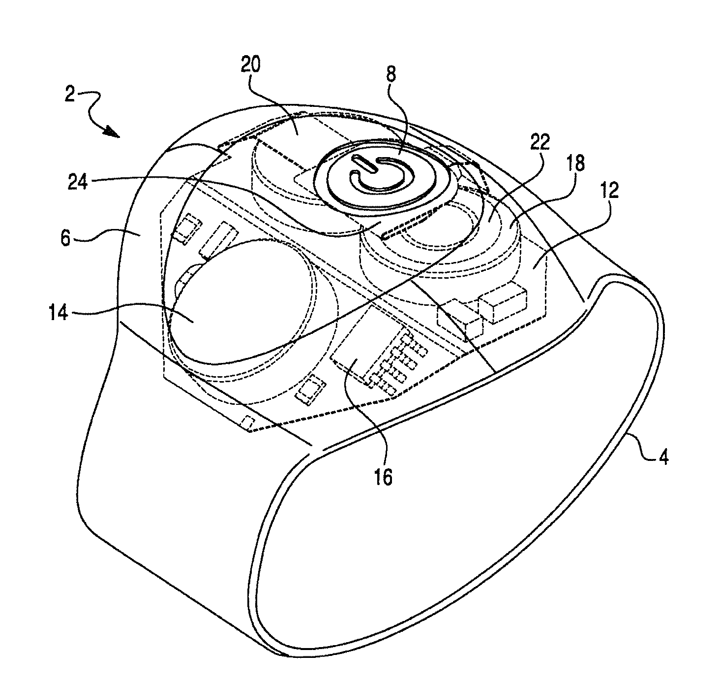
[0018]The present invention is directed to a vibrating band designed to increase the sexual pleasure for the male and his partner during sexual intercourse. It consists of a small vibrating motor or coin motor, one or more small batteries or button batteries, a microprocessor or microcontroller, a touch or push switch, which can be, for example, a dome or momentary switch, and a flexible circuitry board. All components are enclosed inside a soft SEBS (Styrene-Ethylene / Butylene-Styrene) block co-polymer housing portion or over-mold. A male can place the vibrating band anywhere on his penis for intercourse.

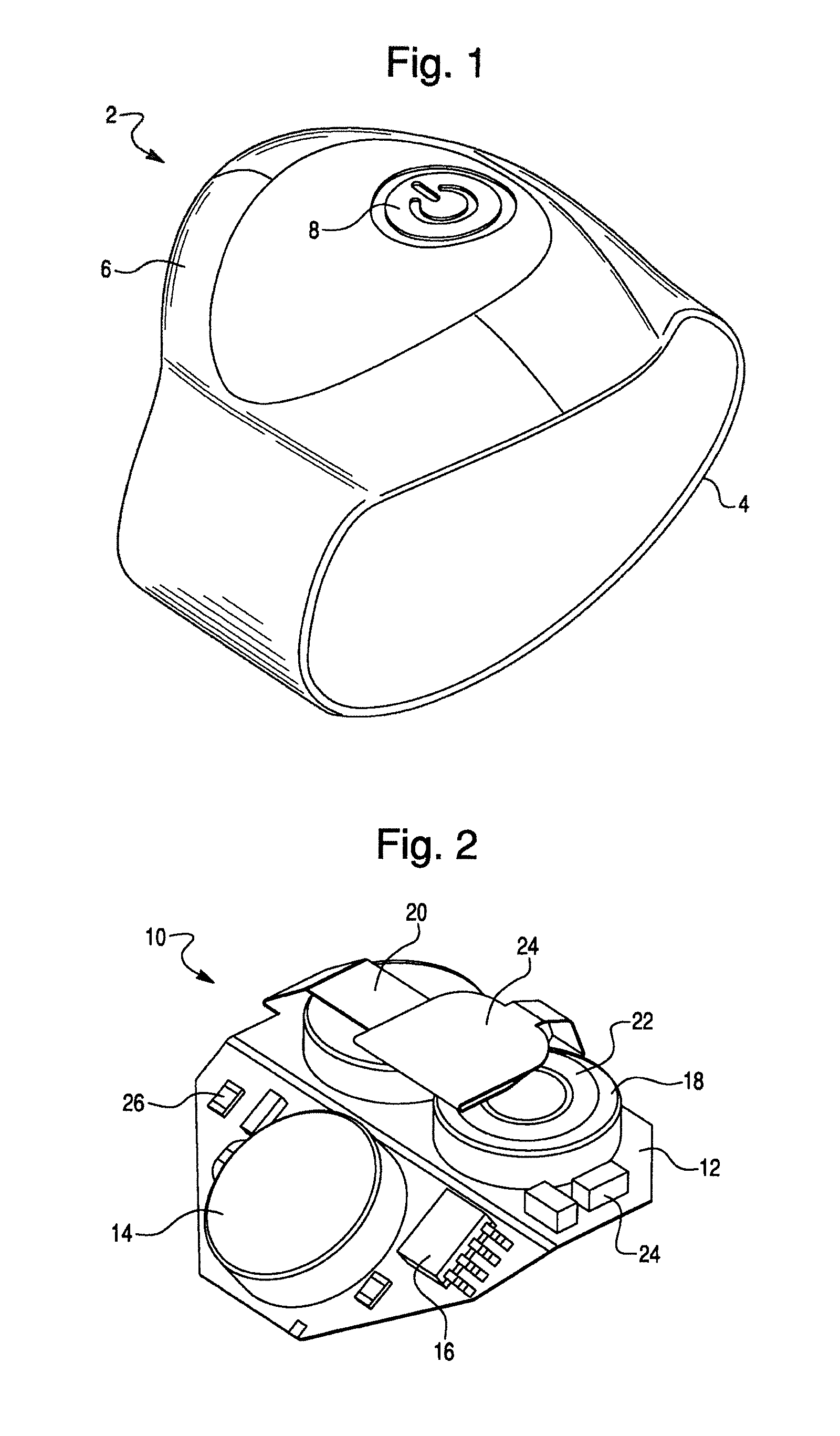
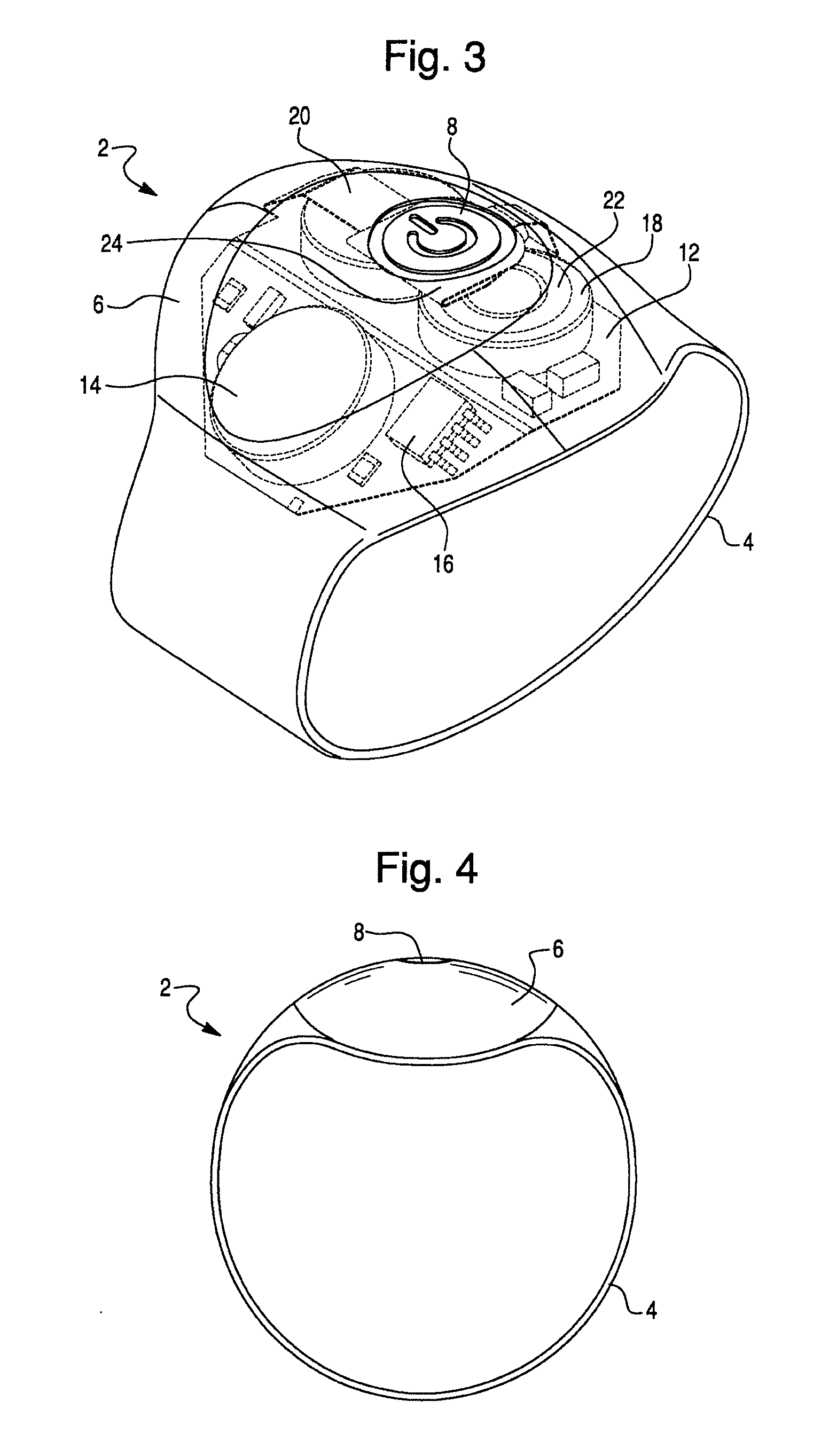
[0019]Referring now to FIG. 1, a perspective view of the vibrating band 2 of the present invention is shown. In accordance with the present invention, the vibrating band 2 comprises an elastic belt-like ring or O-ring 4, a housing portion 6 and a touch or push switch 8, which can be used to operate a vibrating motor (not shown). In one embodiment, the housing portion 6 is sealed to ...


PUM


Abstract

The present invention is directed to a vibrating band comprising a belt-like O-ring, a housing with a vibrating device contained within the housing. The vibrating device comprises a vibrating motor, one or more batteries and a touch or push switch. The vibrating band can be used by a male user to increase stimulation for both the male and his partner during sexual intercourse.

Description

REFERENCE TO RELATED APPLICATIONS This application is related to U.S. Provisional Application Ser. No. 61 / 249,903 filed Oct. 8, 2009, and takes priority therefrom.FIELD OF THE INVENTION[0001]The present invention is directed to a vibrating band, which can be used to enhance sexual pleasure for both the user and the user's partner.BACKGROUND OF THE INVENTION[0002]There historically have been many prior art devices developed to improve or aid sexual gratification, both for men and women. The devices designed for use by women are typically phallic in form and may or may not include a vibration device within. Those without a vibrator are intended for vaginal penetration and stimulation while those that vibrate are also intended for vaginal penetration and stimulation and additionally for clitoral and g-spot stimulation. Although these phallic shaped devices may be used for clitoral stimulation during intercourse, they must be hand held at such times, which limits the possible positions ...

Claims


Application Information

Patent Timeline
IPC IPC(8): A61H1/00
CPCA61H19/50A61H2201/165A61H2201/0111A61H19/40A61H23/02A61H2201/5097A61H19/32A61H11/00
Inventor DYER, ROBERTHARRISON, MICHAEL J.KIEKE, JASONYAM, BENNY S.SMETANA, ALFRED J.GAYLOR, IANBOLKAN, STEVENEVANS, GEMMA
Owner CHURCH & DWIGHT CO INC
Features
  • Generate Ideas
  • Intellectual Property
  • Life Sciences
  • Materials
  • Tech Scout
  • Unparalleled Data Quality
  • Higher Quality Content
  • 60% Fewer Hallucinations
Learn More