Suspension device

a suspension device and suspension technology, applied in the direction of resilient suspensions, vehicle springs, vehicle components, etc., can solve the problems of inability to realize damping force, and achieve the effect of not deteriorating vehicle ride quality

Inactive Publication Date: 2012-07-26
KYB CORP +1
View PDF11 Cites 41 Cited by
  • Summary
  • Abstract
  • Description
  • Claims
  • Application Information

AI Technical Summary

Benefits of technology

[0004]Therefore, the present invention has been conceiving taking the above-mentioned shortcoming into consideration, and sets as an object thereof to provide a suspension device for which a damping force is realized even during failure so that the ride quality is never harmed.
[0006]According to the suspension device of the present invention, the second fluid pressure damper is made to be arranged in parallel to the active suspension unit; therefore, even if the actuator becomes unable to output a thrust force for any, reason and the actuator comes to extend and retract without any resistance, by the second fluid pressure damper realizing a damping force, the vehicle ride quality will not deteriorate even during failure.

Problems solved by technology

However, since the above conventional suspension device connects the actuator with a motor as the driving source to the fluid pressure damper in series, if the motor becomes unable to output torque for any reason and the actuator comes to extend and retract without any resistance, it will become impossible to realize a damping force, and thus, there is a possibility that vehicle ride quality will deteriorate during such a failure.

Method used


Image

  • Suspension device
  • Suspension device
  • Suspension device

Examples


Embodiment Construction

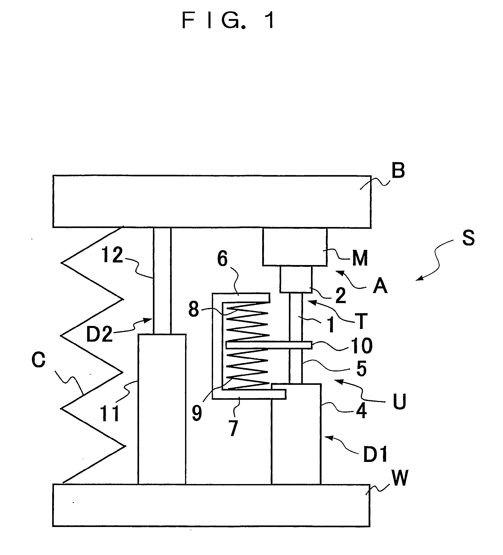
[0011]Hereinafter, the present invention will be explained based on the embodiments shown in the drawings. As shown in FIG. 1, a suspension device S is interposed in parallel with a suspension spring C between a spring lower member W and a spring upper member B, and basically, is configured to include an active suspension unit U provided with a linear actuator A and a first fluid pressure damper D1 that is connected together in a telescoping direction to the actuator A, and a second fluid pressure damper D2 arranged in parallel with the active suspension unit U.

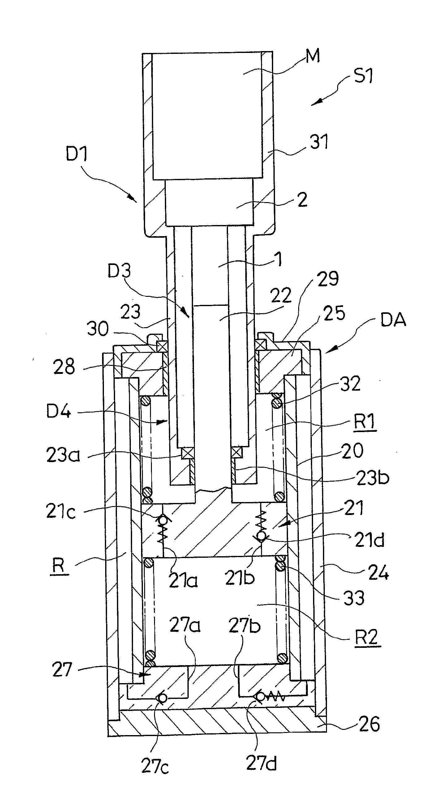
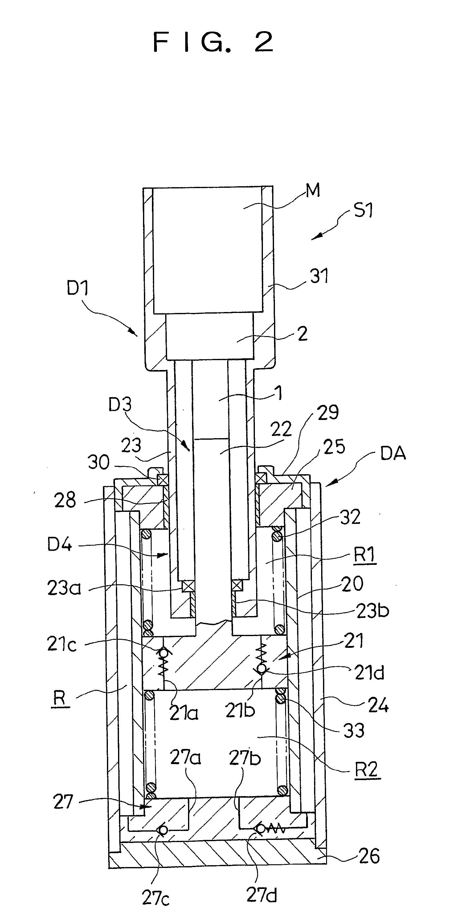
[0012]The actuator A is a linear actuator that extends and retracts, and is configured to include a linear motion member 1, a motion conversion mechanism T that converts the linear motion of the linear motion member 1 into rotational motion of a rotational member 2, and a motor M that is coupled to the rotational member 2, for example. Then, in the case of this actuator A, the extension-retraction operation is enabled by caus...


PUM


Abstract

A suspension device (S) as a solution for the problem of the present invention includes: an active suspension unit (U) equipped with a linear actuator (A) and a first fluid pressure damper (D1) connected to the actuator (A) to extend and retract in the same direction; and a second fluid pressure damper (D2) arranged in parallel with the active suspension unit (U).

Description

FIELD OF THE INVENTION[0001]The present invention relates to an improvement in a suspension device that suppresses relative movement between a vehicle body and vehicle axle with the electromagnetic force generated in a motor.DESCRIPTION OF THE RELATED ART[0002]As this type of suspension device, Japanese Patent Application Laid-Open No. 2008-95800 discloses a device that is configured to include: an actuator having a threaded shaft, a ball screw nut that is rotatably threaded to the threaded shaft, and a motor coupled to the ball screw nut; and a fluid pressure damper in which a rod is coupled to the threaded shaft, the device being interposed between the body and axle of a vehicle by coupling the motor to the body side and a cylinder of the fluid pressure damper to the axle side, and actively controlling the relative movement between the body and axle with the thrust force of the actuator.DISCLOSURE OF THE INVENTION[0003]However, since the above conventional suspension device connec...

Claims


Application Information

Patent Timeline
Patent Type & Authority Applications(United States)
IPC IPC(8): B60G17/00B60G15/12B60G13/06
CPCB60G11/58B60G13/14B60G17/0157B60G17/021B60G17/08B60G2300/60B60G2202/42B60G2202/44B60G2204/419B60G2206/41B60G2202/32
Inventor KONDO, TAKUHIROKOBAYASHI, YOSHIFUMIHONMA, MOTOHIKOTACHI, TAKAYUKI
Owner KYB CORP
Why Eureka
Try Eureka