Light source lighting device and luminaire

a technology of lighting device and light source, which is applied in the direction of electric variable regulation, process and machine control, instruments, etc., can solve the problem that the speed cannot catch up with the lighting response speed

Inactive Publication Date: 2012-07-26
MITSUBISHI ELECTRIC CORP
View PDF5 Cites 52 Cited by
  • Summary
  • Abstract
  • Description
  • Claims
  • Application Information

AI Technical Summary

Benefits of technology

[0026]According to the power supply circuit of the present invention, light-emitting elements (LED series circuits each formed of a plurality of LEDs connected in series) which require

Problems solved by technology

This speed cannot catch up with the

Method used


Image

  • Light source lighting device and luminaire
  • Light source lighting device and luminaire
  • Light source lighting device and luminaire

Examples


embodiment 1

[0036]A power supply circuit 100 (light source lighting device) of the first embodiment will be described with reference to FIGS. 1 to 7.

(Configuration of Luminaire 800)

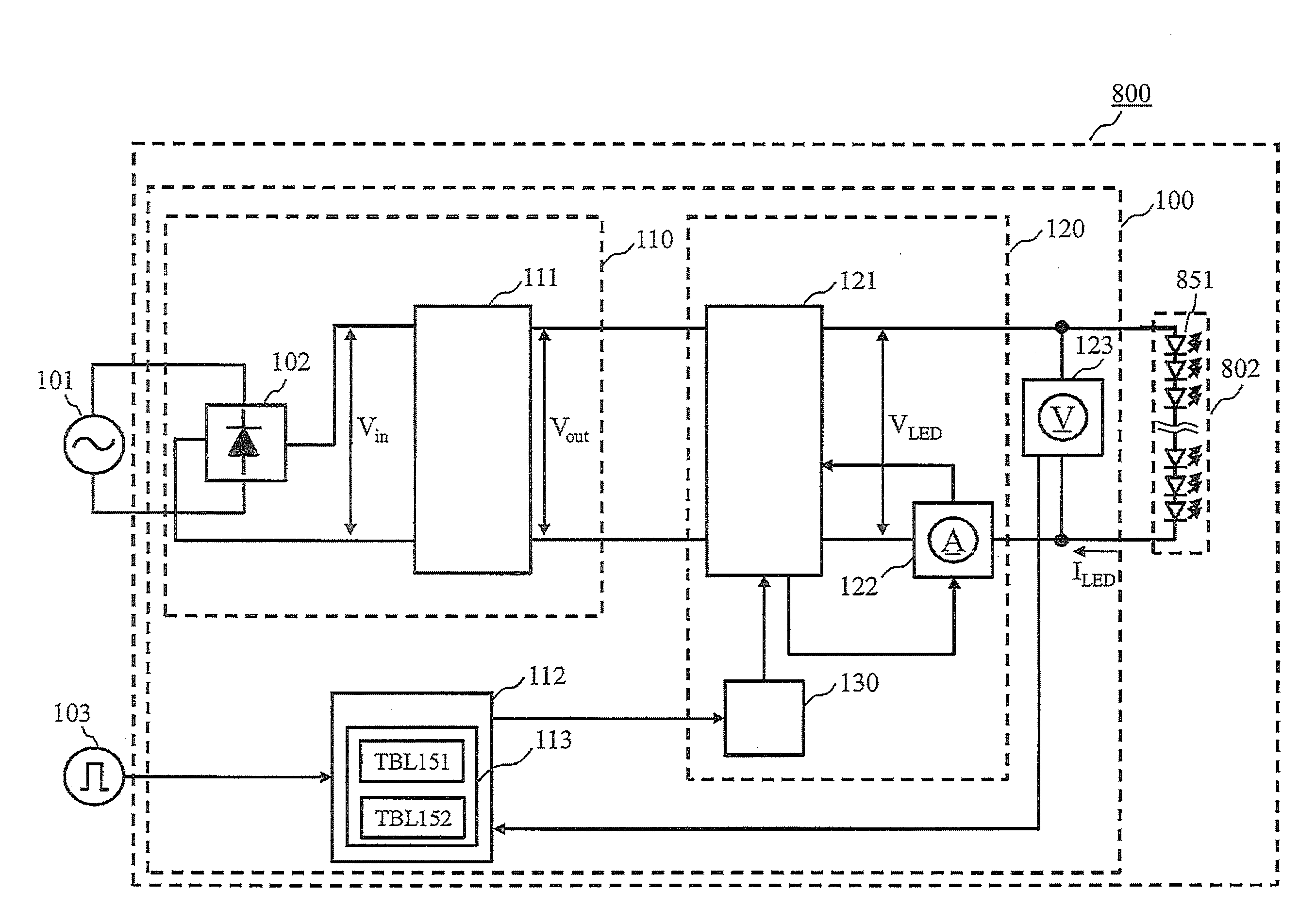
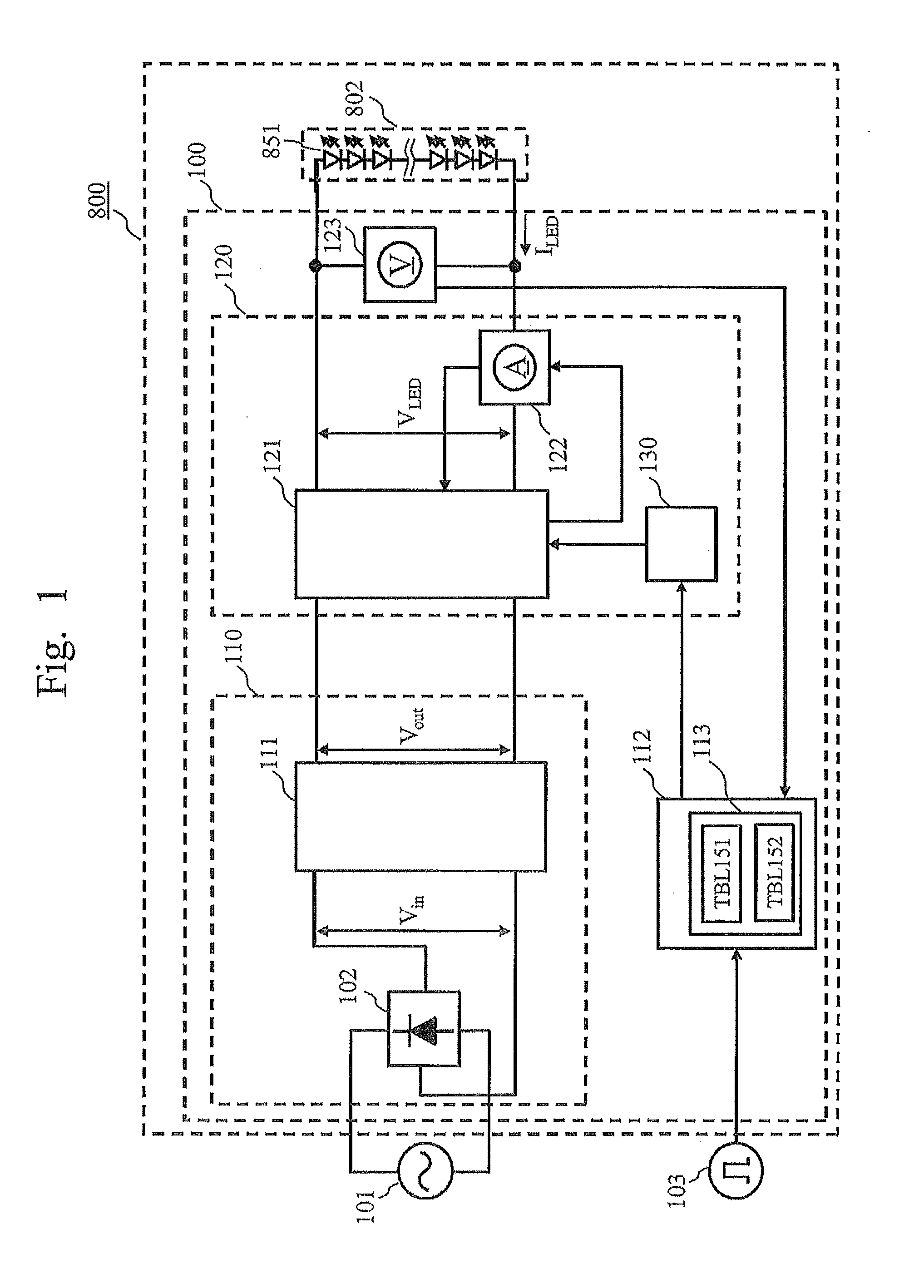
[0037]FIG. 1 is a block diagram of a luminaire 800 provided with the power supply circuit 100. After reception of AC power from a commercial power supply 101, the luminaire 800 lights a light-emitting element such as an LED or organic EL. The luminaire 800 incorporates the power supply circuit 100 and a light-emitting element 802.

(Light-Emitting Element 802)

(1. Definition of Light-Emitting Element)

[0038]The “light-emitting element 802” (light source) used in the first embodiment refers to an LED module formed of an LED series circuit 851 in which a plurality of LEDs are connected in series, as shown as the light-emitting element 802 in FIG. 1 (described later). For example, the light-emitting element 802 is an LED series circuit 851 composed of 40 LEDs connected in series. The light-emitting element 802 is connected ...


PUM


Abstract

A power supply circuit drives circuits having different numbers of series-connected LEDs without changing a circuit constant or a component. An LED series circuit is connected to a power converter circuit of a power supply circuit. The power converter circuit is controlled by a control arithmetic circuit, and supplies a constant current to the LED series circuit. A voltage detection circuit detects a voltage applied to the LED series circuit. The control arithmetic circuit checks whether the LED series circuit has 40 LEDs or 20 LEDs, based on the voltage detected by the voltage detection circuit. The control arithmetic circuit holds a constant-current value table for 40 LEDs and a constant-current value table for 20 LEDs. In accordance with the detected voltage, the control arithmetic circuit selects one constant-current value table, and controls the power converter circuit based on the constant-current value table selected.

Description

CROSS-REFERENCE TO RELATED APPLICATIONS[0001]This application is based on and claims the benefit of priority from Japanese Patent Application No. 2011-011342, filed in Japan on Jan. 21, 2011, the content of which is incorporated herein by reference in its entirety.TECHNICAL FIELD[0002]The present invention relates to a light source lighting device which lights a light source, and a luminaire provided with the light source lighting device.BACKGROUND ART[0003]As a power supply circuit which converts electric power supplied from an AC power supply such as a commercial power supply into a DC for lighting a light-emitting element such as a light-emitting diode (to be referred to as an “LED” hereinafter) or an organic electroluminescence (to be referred to as an “organic EL” hereinafter), a combination of a power factor correction circuit and a power converter circuit is known. The power factor correction circuit is a circuit that approximates the input power factor to 1 so that the power...

Claims


Application Information

Patent Timeline
IPC IPC(8): H05B37/02
CPCY02B20/347H05B33/0815H05B45/3725H05B45/375Y02B20/30
Inventor NONAKA, TAKAFUMIKUMAGAI, TAKASHIITO, YUICHIROKINOSHITA, HARUKAFUNAYAMA, SHINSUKEMAEDA, TAKASHI
Owner MITSUBISHI ELECTRIC CORP
Why Eureka
Try Eureka