PWM controller with constant output power limit for a power supply

a power supply and controller technology, applied in the field of power supply, can solve the problems of difficult to design a precise resistor inside the integrated circuit, and achieve the effects of reducing power consumption, reducing power supply size, and reducing power consumption

Active Publication Date: 2006-08-29
BCD SHANGHAI MICRO ELECTRONICS CO LTD
View PDF9 Cites 139 Cited by
  • Summary
  • Abstract
  • Description
  • Claims
  • Application Information

AI Technical Summary

Benefits of technology

[0016]The present invention provides a PWM controller having a line voltage input that allows using one resistor for chip start-up and line voltage sensing so that it can save the power consumption, ease the PCB lay

Problems solved by technology

A resistor is needed to transform the current to the voltage, however it

Method used


Image

  • PWM controller with constant output power limit for a power supply
  • PWM controller with constant output power limit for a power supply
  • PWM controller with constant output power limit for a power supply

Examples


Embodiment Construction

[0024]The detailed descriptions for content and technology of the present invention associated with figures are as follows.

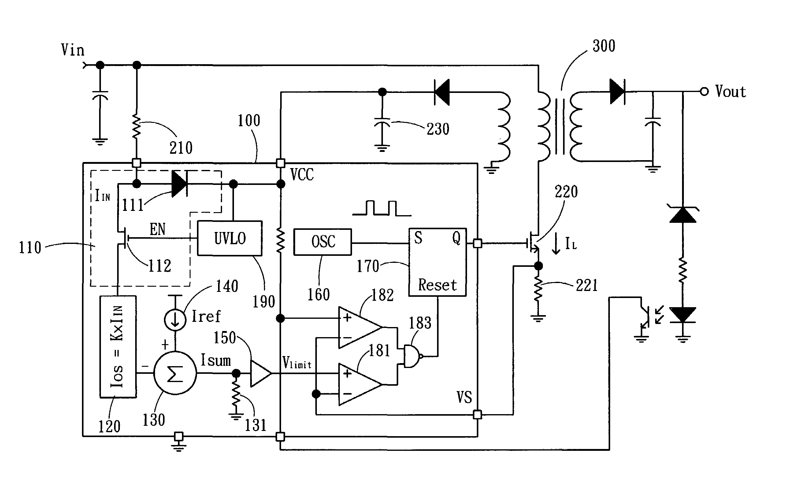
[0025]Please refer to FIG. 3. It is the block diagram of the PWM controller of a preferred embodiment of the present invention and connected circuits therewith. The PWM controller 100 comprises a current switch unit 110 composed of a diode 111, a switch transistor 112, a current multiplier 120, a current adder 130, a reference current 140, a buffer 150, an oscillator 160, a flip-flop 170, a first comparator 181, a second comparator 182, a NAND gate 183 and an under-voltage lockout unit 190.

[0026]The drain of the switch transistor 112 and the anode of the diode 111 are connected to form an input of the current switch unit 110. A start-up resistor 210 is connected between the input voltage Vin and the input of the current switch unit 110. The cathode of the diode 111 is connected to the power supply voltage VCC. The gate of the switch transistor 112 is controlled ...


PUM


Abstract

A PWM controller has a line voltage input that allows using a start-up resistor for both start-up and power-limit compensations so that it can save the power consumption, ease the PCB layout, and shrink the power supply size. In the integrated circuit, a current switch used for both start-up and line voltage sensing is composed of a diode and a switch transistor. A current multiplier is used to improve the precise by canceling the impact of the integrated resistor's absolute value, which is composed of a transistor loop, a constant current and a reference current. Thus, by properly selecting the value of the start-up resistor, an identical output power limit for low line and high line voltage input can be achieved.

Description

FIELD OF THE INVENTION[0001]The present invention relates to a power supply. More particularly, the present invention relates to the pulse width modulation (PWM) of a switching mode power converter.BACKGROUND OF THE INVENTION[0002]The PWM is a traditional technology used in the switching mode power converter to control the output power and achieve the regulation. Most of the equipments, such as mobile phone, TV game, computer and so on are using PWM power converters to supply power and charge battery. Various protection functions such as over-voltage and over-current protection are built in the power supply to protect the power supply and the load from permanent damage. The function of output power limit is generally used for the over-load and short circuit protection.[0003]Referring to FIG. 1, it shows a conventional application circuit of the PWM power supply. A PWM controller 10 controls the power output and achieves the regulation. The operation of PWM-control starts on the char...

Claims


Application Information

Patent Timeline
IPC IPC(8): H02M3/335
CPCH02M3/33523H02M1/36
Inventor YING, ZHENG
Owner BCD SHANGHAI MICRO ELECTRONICS CO LTD
Why Eureka
Try Eureka