

Capacitive load driving circuit, capacitive load driving method, and driving circuit for liquid crystal display device
- Summary
- Abstract
- Description
- Claims
- Application Information
AI Technical Summary
Benefits of technology
Problems solved by technology
Method used
Image

Examples
first embodiment
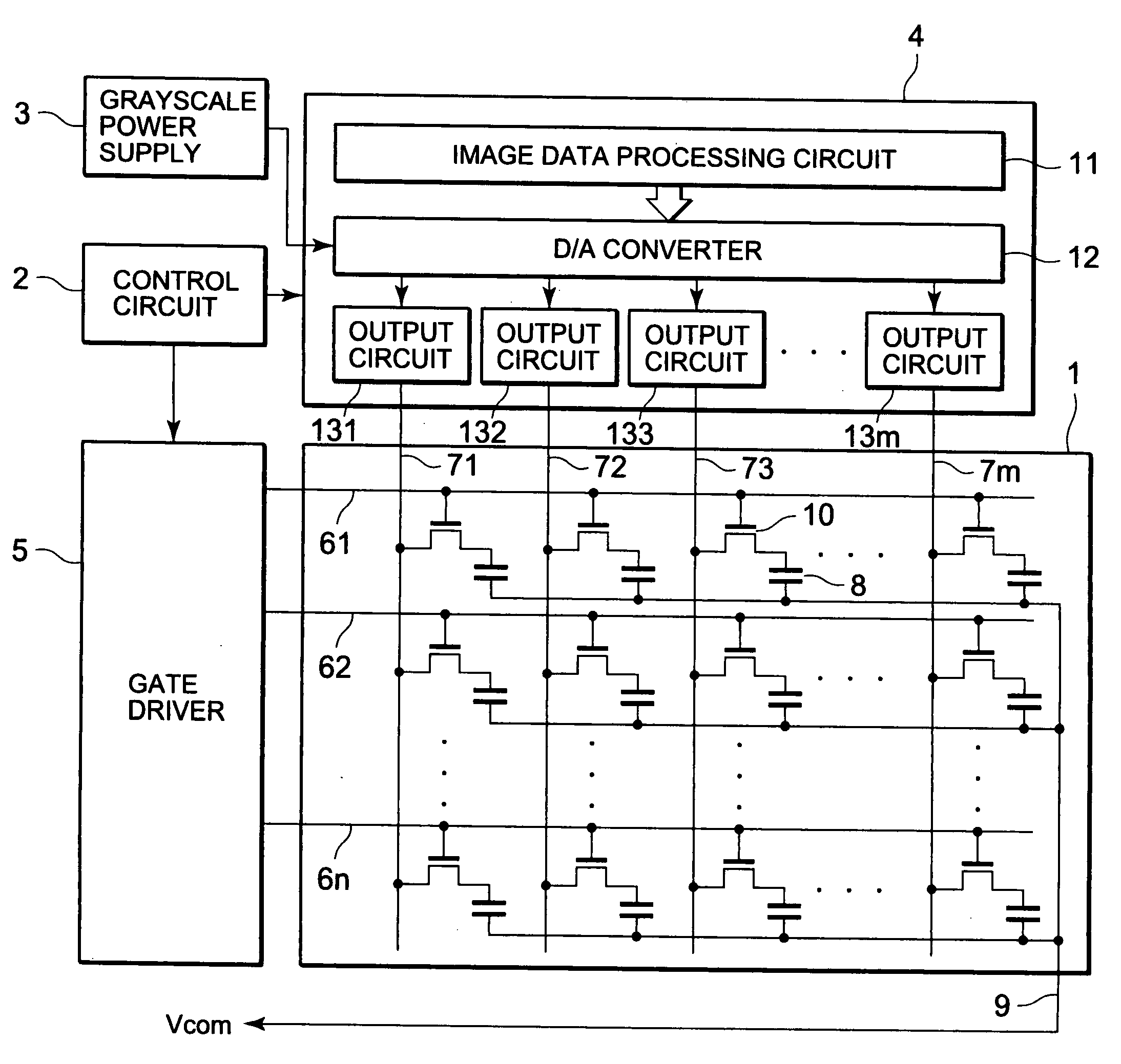
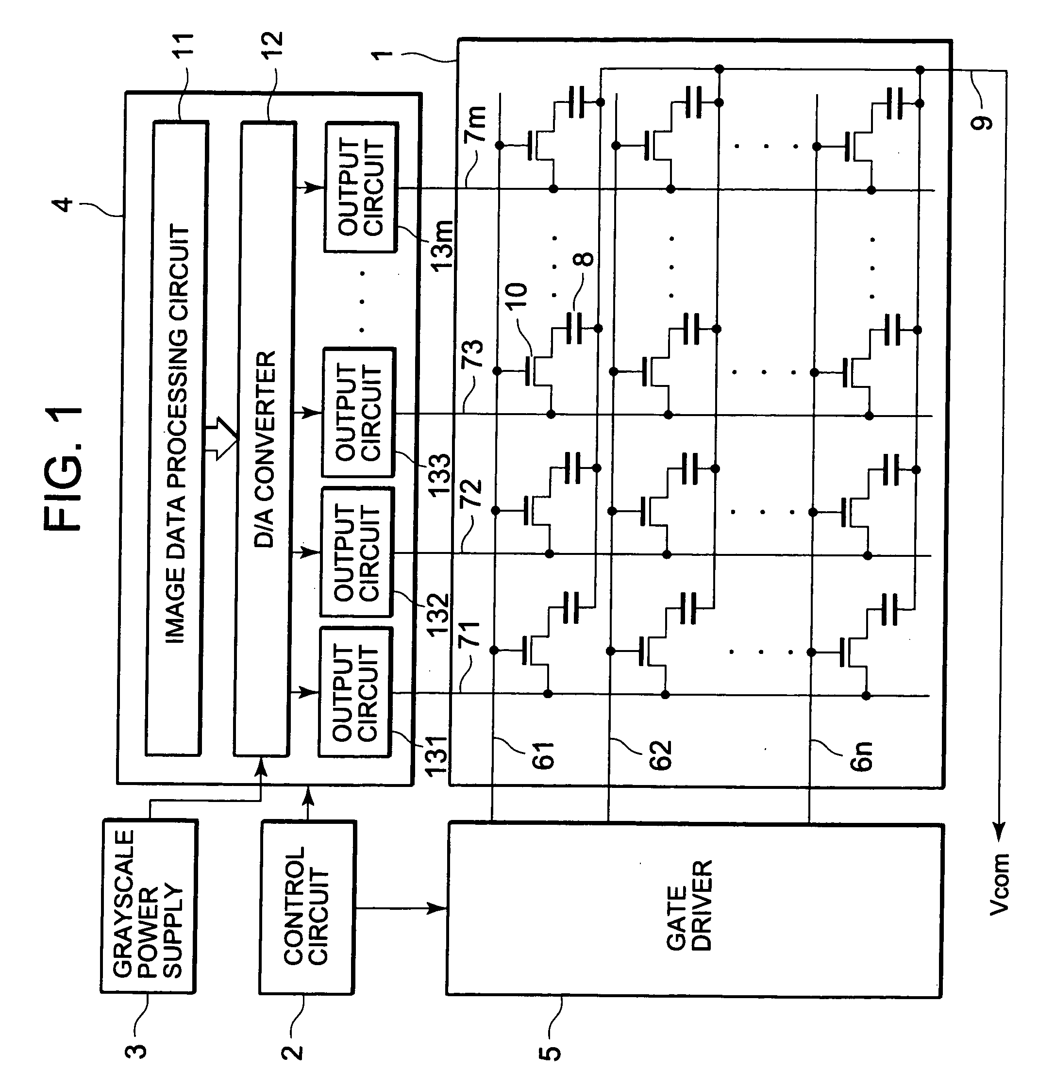
[0053]FIG. 1 is a block diagram showing a configuration of a liquid crystal display device according to a first embodiment of the present invention. The configuration of this liquid crystal display device is the same as that of the liquid crystal display device described in the section describing the related art, but will be described below once again. The liquid crystal display device according to the first embodiment has a system in which an analog data signal generated based on digital image data is applied to a liquid crystal panel. The liquid crystal display device includes a liquid crystal panel 1, a control circuit 2, a grayscale power supply circuit 3, a data electrode driving circuit (source driver) 4, and a scan electrode driving circuit (gate driver) 5.
[0054]The liquid crystal panel 1 has an active matrix drive system in which a thin film transistor (TFT) is used as a switch element. In the liquid crystal panel 1, pixels are respectively formed of regions encompassed by n...
second embodiment
[0103]In the first embodiment described above, the voltage for pre-charge of the arithmetic amplifier having the pre-charge (overdrive) function is fixed to the positive power supply voltage (VDD) or to a negative power supply voltage (VSS), and the driving is optimized by changing the pre-charge time. In the second embodiment, the pre-charge time is constant, and the driving is optimized by changing the pre-charge voltage (i.e. voltage difference from a desired voltage). Since the only difference from the first embodiment is the output circuit 13, the description of the liquid crystal display device as a whole will be omitted below.
[0104]FIG. 17 shows one circuit of each of the digital / analog converter 12 and the output circuit 13 of the source driver 4. The output circuit 13 includes the most-significant bit determination circuit 27, a switch control circuit 30, a pre-charge voltage control circuit 31, and an LCD-driving amplification circuit 60. The digital image signal outputted...
PUM
 Abstract
Description
Claims
Application Information