
Numerical controller having workpiece mounting error compensation unit for three-axis machine tool

a technology of compensation unit and machine tool, which is applied in the direction of electric programme control, program control, instruments, etc., can solve the problems of inability to apply three-axis machine tool methods, workpiece mounting error (offset) caused by machine tool, and inability to compensate the direction of the tool

Active Publication Date: 2012-07-26
FANUC LTD
View PDF6 Cites 10 Cited by
  • Summary
  • Abstract
  • Description
  • Claims
  • Application Information

AI Technical Summary

Benefits of technology

[0016]An object of the present invention is to provide a numerical controller that precisely compensates a tool center point position, which is a machining point, when there is a mounting error of a workpiece in a three-axis machine tool having at least three linear axes.
[0023]The present invention can provide a numerical controller that can precisely compensate a tool center point position, which is a machining point, when there is a mounting error of a workpiece in a three-axis machine tool having at least three linear axes. According to the present invention, the tool center point position that is the machining point can be made correct with respect to the workpiece, although the direction of the tool cannot be compensated. Therefore, the machining at a tool center point can precisely be carried out.

Problems solved by technology

In this case, a workpiece mounting error (offset) is caused with respect to the machine tool because of the usage of the jig or the tilt of the table.
Therefore, these methods cannot be applied to a three-axis machine tool.
However, since the three-axis machine tool has no rotary axis, the direction of the tool cannot be compensated.
This suggests that a translational error can be compensated by setting a workpiece offset, but a rotation error cannot accurately be compensated by the three-dimensional coordinate conversion function.

Method used


Image

  • Numerical controller having workpiece mounting error compensation unit for three-axis machine tool
  • Numerical controller having workpiece mounting error compensation unit for three-axis machine tool
  • Numerical controller having workpiece mounting error compensation unit for three-axis machine tool

Examples


first embodiment

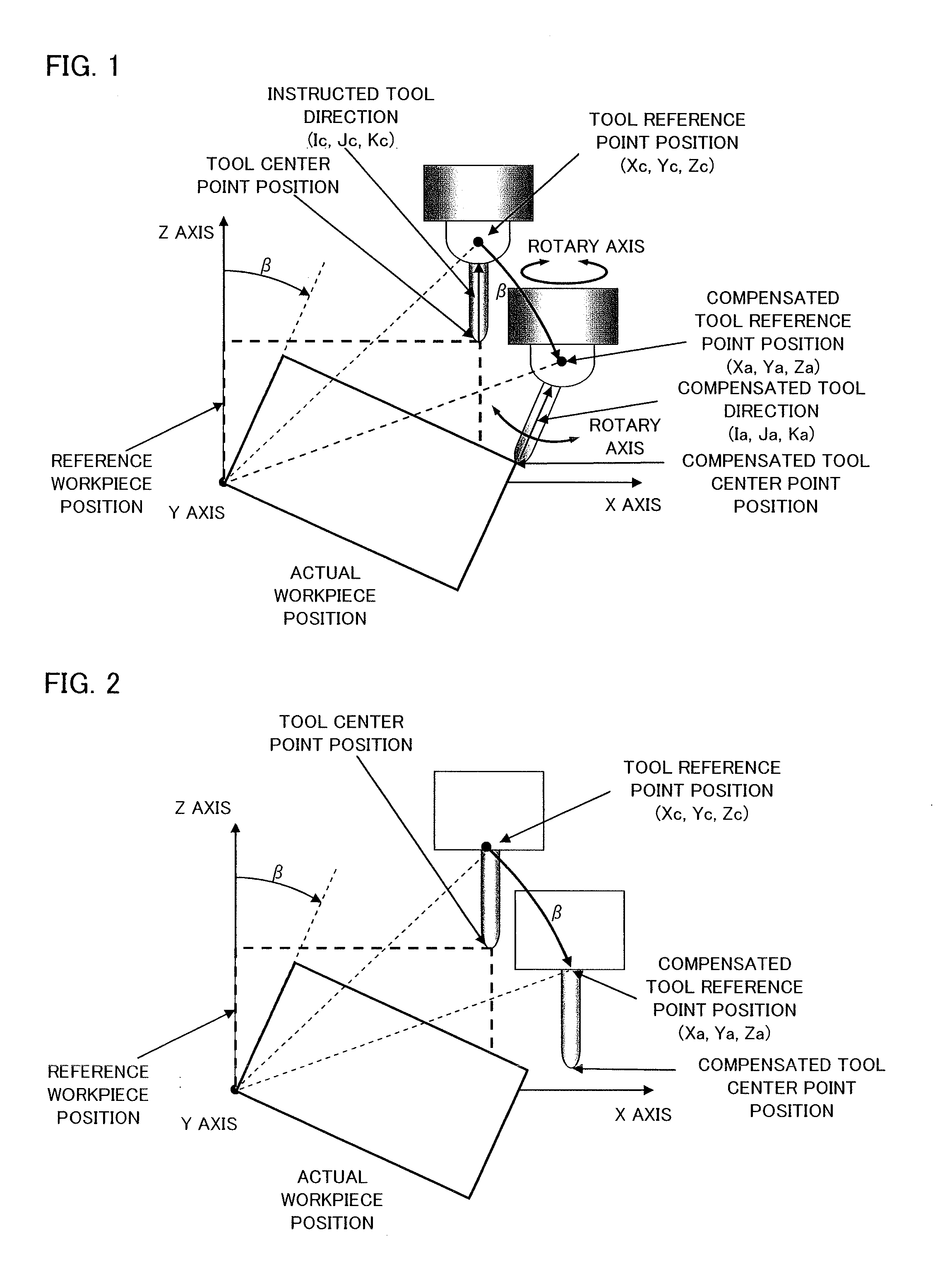
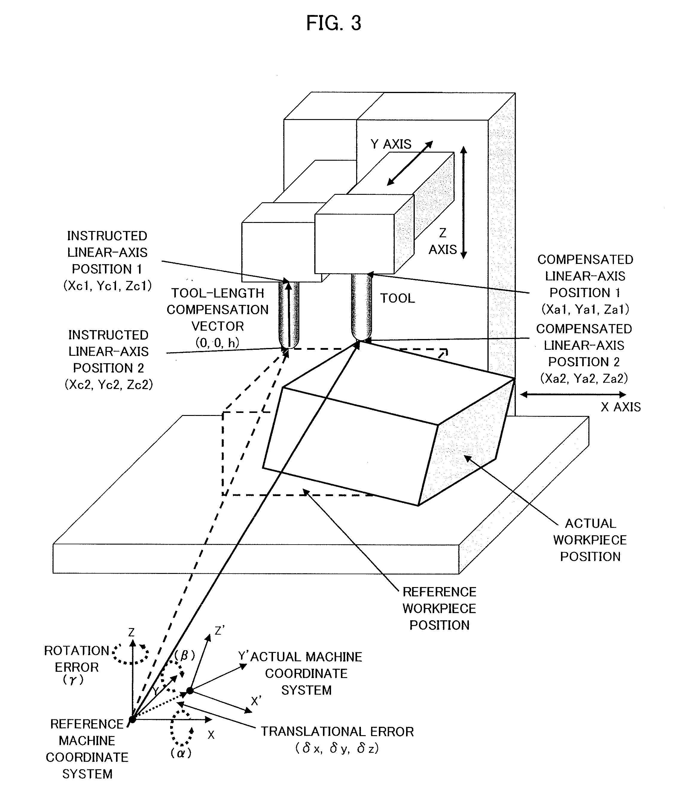
[0038]When the tool reference point position is instructed, a calculation in an equation (3) is carried out with respect to the instructed linear-axis position 1 (Xc1, Yc1, Zc1), whereby a compensated linear-axis position 1 (Xa1, Ya1, Za1) is obtained. It is an error compensation unit in the workpiece mounting error compensation unit that carries out this calculation. The instructed linear-axis position 1 is the instructed linear-axis position. The compensated linear-axis position 1 is a compensated linear-axis position. The position where the X, Y, and Z axes actually move is the compensated linear-axis position 1 (Xa1, Ya1, Za1). The three linear axes are driven to this position (see FIG. 5). With this, even when the tool reference point position is instructed, the compensated tool center point position that is the machining point (the compensated linear-axis position 2 (Xa2, Ya2, Za2) in FIG. 3) becomes a correct position with respect to the actual workpiece position. Therefore, ...

second embodiment

[0042]In case where the tool center point position is instructed as the instructed linear-axis position 2 (Xc2, Yc2, Zc2), the tool-length compensation vector (0, 0, h) is added to the instructed linear-axis position 2 (Xc2, Yc2, Zc2) to obtain the instructed tool reference point position, and the instructed tool reference point position thus obtained is specified as the instructed linear-axis position 1 (Xc1, Yc1, Zc1). The calculation in the equation (3) is carried out for the instructed linear-axis position 1 (Xc1, Yc1, Zc1) as in the above-mentioned first embodiment, whereby the compensated linear-axis position 1 (Xa1, Ya1, Za1) is obtained. It is an error compensation unit in the workpiece mounting error compensation unit that carries out this calculation. The instructed linear-axis position 1 is the instructed linear-axis position. The compensated linear-axis position 1 is a compensated linear-axis position. The position where the X, Y, and Z axes actually move is the compensa...


PUM


Abstract

A numerical controller controls a three-axis machine tool that machines a workpiece, mounted on a table, with at least three linear axes. The numerical controller includes a workpiece mounting error compensation unit that compensates a mounting error caused when the workpiece is mounted. The workpiece mounting error compensation unit performs an error compensation with respect to an instructed linear-axis position with amounting error which is set beforehand, in order to keep a position with respect to the workpiece at a tool center point position, based on the instructed linear-axis position of the three linear axes to obtain a compensated linear-axis position. The three linear axes are driven based on the obtained compensated linear-axis position.

Description

BACKGROUND OF THE INVENTION[0001]1. Field of the Invention[0002]The present invention relates to a numerical controller that controls a three-axis machine tool, which machines a workpiece (an object to be machined) mounted on a table with at least three linear axes, and more particularly, to a numerical controller having a workpiece mounting error compensation unit for a three-axis machine tool that compensates a mounting error caused when a workpiece is mounted.[0003]2. Description of the Related Art[0004]A jig for fixing a workpiece on a table is used in order to facilitate a machining with a use of a machine tool. In this case, a workpiece mounting error (offset) is caused with respect to the machine tool because of the usage of the jig or the tilt of the table. The mounting error described above has to be compensated.[0005]For example, Japanese patent documents described below describe techniques for compensating a mounting error of the workpiece with respect to the table when t...

Claims


Application Information

Patent Timeline
IPC IPC(8): G05B19/25
CPCG05B19/4086
Inventor OTSUKI, TOSHIAKIIDE, SOICHIROHANAOKA, OSAMUSASAKI, TAKAFUMI
Owner FANUC LTD
Learn More