Moving picture coding method, moving picture coding apparatus, moving picture decoding method, moving picture decoding apparatus, and moving picture coding and decoding apparatus

a coding method and coding apparatus technology, applied in the direction of signal generators with optical-mechanical scanning, color television with bandwidth reduction, signal generation, etc., can solve problems such as reducing coding efficiency, and achieve the effect of increasing coding efficiency

Inactive Publication Date: 2012-07-26
PANASONIC CORP
View PDF3 Cites 76 Cited by
  • Summary
  • Abstract
  • Description
  • Claims
  • Application Information

AI Technical Summary

Benefits of technology

[0015]The present invention has been conceived to solve the above problem, and an object of the present invention is to provide a moving picture coding method and a moving picture decoding method which make it possible to derive a motion vector most suitable for a current picture to be coded and to increase coding efficiency.
[0017]With this configuration, it is possible to derive the motion vector most suitable for the current picture and the reference picture as well as to increase the coding efficiency.
[0032]The present invention makes it possible to derive the motion vector most suitable for the current picture and the reference picture and to increase the coding efficiency.

Problems solved by technology

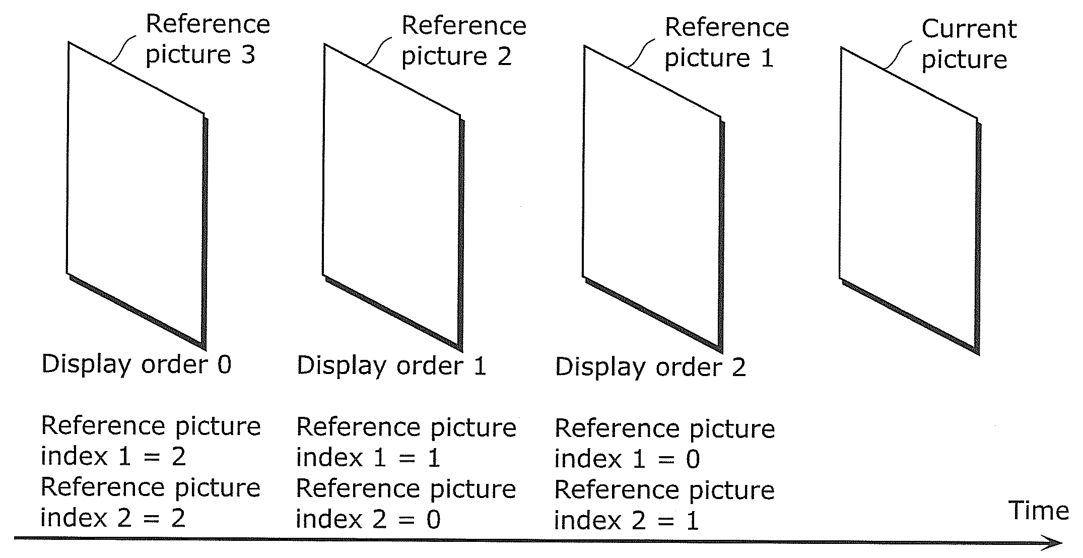
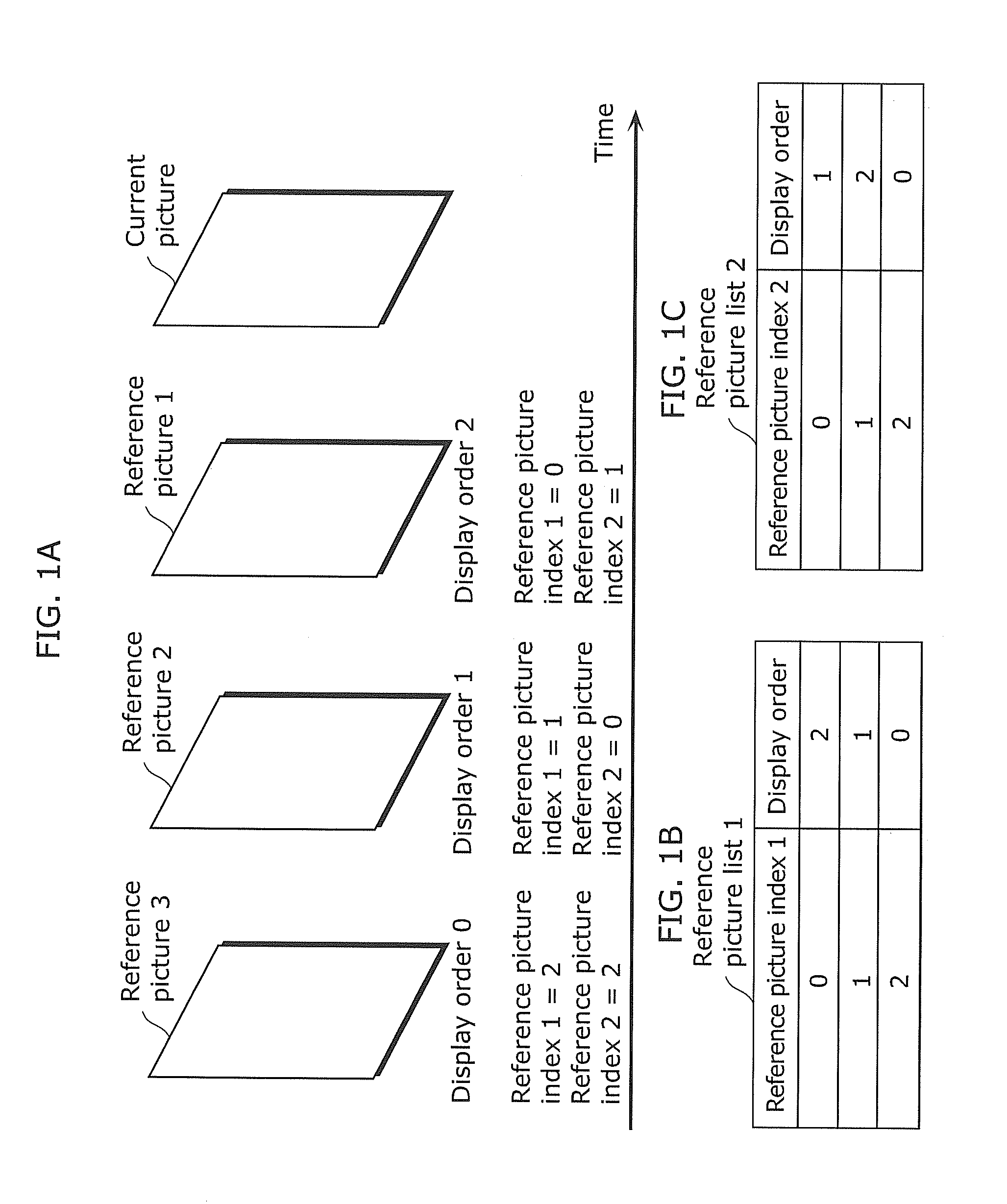
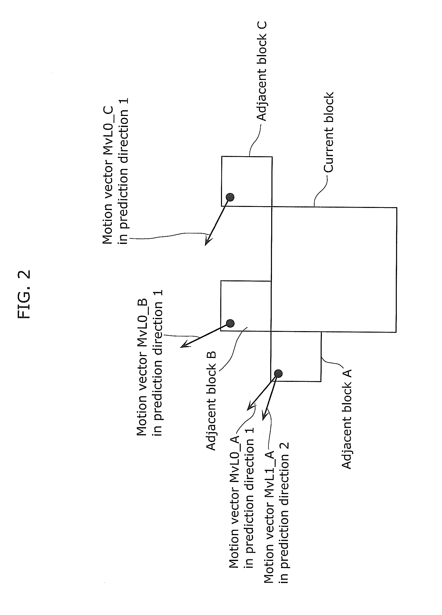
However, in a conventional method for determining a prediction direction in skip mode or direct mode, since the bidirectional prediction is always selected although, for instance, the estimation accuracy of the motion vector MvL1_A in the prediction direction 1 of the adjacent block A shown in FIG. 2 is low, a prediction picture in the skip mode or the direct mode is deteriorated, which leads to the reduction in coding efficiency.

Method used


Image

  • Moving picture coding method, moving picture coding apparatus, moving picture decoding method, moving picture decoding apparatus, and moving picture coding and decoding apparatus
  • Moving picture coding method, moving picture coding apparatus, moving picture decoding method, moving picture decoding apparatus, and moving picture coding and decoding apparatus
  • Moving picture coding method, moving picture coding apparatus, moving picture decoding method, moving picture decoding apparatus, and moving picture coding and decoding apparatus

Examples


embodiment 1

[0130]FIG. 3 is a block diagram showing a configuration of a moving picture coding apparatus using a moving picture coding method according to Embodiment 1 of the present invention.

[0131]A moving picture coding apparatus 100 includes, as shown in FIG. 3, an orthogonal transform unit 101, a quantization unit 102, an inverse quantization unit 103, an inverse orthogonal transform unit 104, a block memory 105, a frame memory 106, an intra prediction unit 107, an inter prediction unit 108, an inter prediction control unit 109, a picture type determination unit 110, a reference picture list management unit 111, a skip mode prediction direction determination unit 112, and a variable-length coding unit 113. The orthogonal transform unit 101 transforms, from image domain into frequency domain, prediction error data between prediction picture data generated by a unit to be described later and an input picture sequence. The quantization unit 102 performs a quantization process on the predictio...

embodiment 2

[0174]FIG. 14 is a block diagram showing a configuration of a moving picture coding apparatus using a moving picture coding method according to Embodiment 2 of the present invention. A moving picture coding apparatus 200 according to this embodiment includes a skip mode prediction direction addition determination unit instead of the skip mode prediction direction determination unit in Embodiment 1. A configuration of this embodiment differs from that of Embodiment 1 in that when a skip mode prediction direction addition flag is ON, an inter prediction direction is added for each current block to be coded even in the skip mode. It is to be noted that the same reference signs are assigned to the same elements as in Embodiment 1, and a description thereof is omitted.

[0175]A skip mode prediction direction addition determination unit 201 determines, through a method to be described later, whether or not an inter prediction direction is to be added for each current block to be coded even ...

embodiment 3

[0188]FIG. 18 is a block diagram showing a configuration of a moving picture coding apparatus using a moving picture coding method according to Embodiment 3 of the present invention. A moving picture coding apparatus 300 according to this embodiment differs from the moving picture coding apparatus according to Embodiment 1 in that a skip mode prediction direction flag generated by the skip mode prediction direction determination unit is added to header information (e.g., a picture parameter set or a slice header in H.264) which is given to a bitstream for each unit of processing such as a picture. It is to be noted that the same reference signs are assigned to the same elements as in Embodiment 1, and a description thereof is omitted.

[0189]As in Embodiment 1, a skip mode prediction direction determination unit 301 determines a skip mode prediction direction for a current block to be coded, and sets a skip mode prediction direction flag. In addition, the skip mode prediction directio...


PUM


Abstract

A moving picture coding apparatus includes: a reference picture list management unit which assigns a reference picture index to each reference picture and creates reference picture lists together with display order and the like; a skip mode prediction direction determination unit which determines a prediction direction in a skip mode for a current block to be coded, using the reference picture lists; and an inter prediction control unit which compares a cost of a motion vector estimation mode, a cost of a direct mode, and a cost of the skip mode in which a prediction picture is generated using a predicted motion vector generated according to the prediction direction determined by the skip mode prediction direction determination unit, and determines a more efficient inter prediction mode among the three modes.

Description

CROSS REFERENCE TO RELATED APPLICATION[0001]The present application claims the benefit of U.S. Provisional Patent Application No. 61 / 436,358 filed Jan. 26, 2011. The entire disclosures of the above-identified applications, including the specifications, drawings and claims are incorporated herein by reference in their entirety.BACKGROUND OF THE INVENTION[0002](1) Field of the Invention[0003]The present invention relates to a moving picture coding method for coding an input picture on a block-by-block basis using inter picture prediction in which coded pictures are referred to, and to a moving picture decoding method for decoding a bitstream on a block-by-block basis using the inter picture prediction.[0004](2) Description of the Related Art[0005]In moving picture coding processing, a quantity of information is generally reduced using redundancy of moving pictures in spatial and temporal directions. Here, a general method using the redundancy in the spatial direction is represented by...

Claims


Application Information

Patent Timeline
Patent Type & Authority Applications(United States)
IPC IPC(8): H04N7/26H04N19/94
CPCH04N19/176H04N19/147H04N19/19H04N19/132H04N19/109
Inventor SUGIO, TOSHIYASUNISHI, TAKAHIROSHIBAHARA, YOUJISASAI, HISAO
Owner PANASONIC CORP
Why Eureka
Try Eureka