Self-releasing structural assembly

Active Publication Date: 2012-08-02
HATZINIKOLAS MICHAEL
View PDF6 Cites 3 Cited by
  • Summary
  • Abstract
  • Description
  • Claims
  • Application Information

AI Technical Summary

Benefits of technology

[0014]Optionally, the fusible member may also have a channel through which the securing member extends. In operation, the fusible member may not necessarily have to burn all the way though to permit release of the structural member, be it a floor or ceiling member, from the firewall. Release may occur shortly after the break-away connector system is subjected to heat. This may allow the structural components to separate from one another sooner, thereby increasing the duration of time for which a firewall remains intact.

Problems solved by technology

When there is a fire on one side of the fire barrier member, the break-away clips may melt and disengage the structural member from the remainder of the wall structure.

Method used


Image

  • Self-releasing structural assembly
  • Self-releasing structural assembly
  • Self-releasing structural assembly

Examples


Embodiment Construction

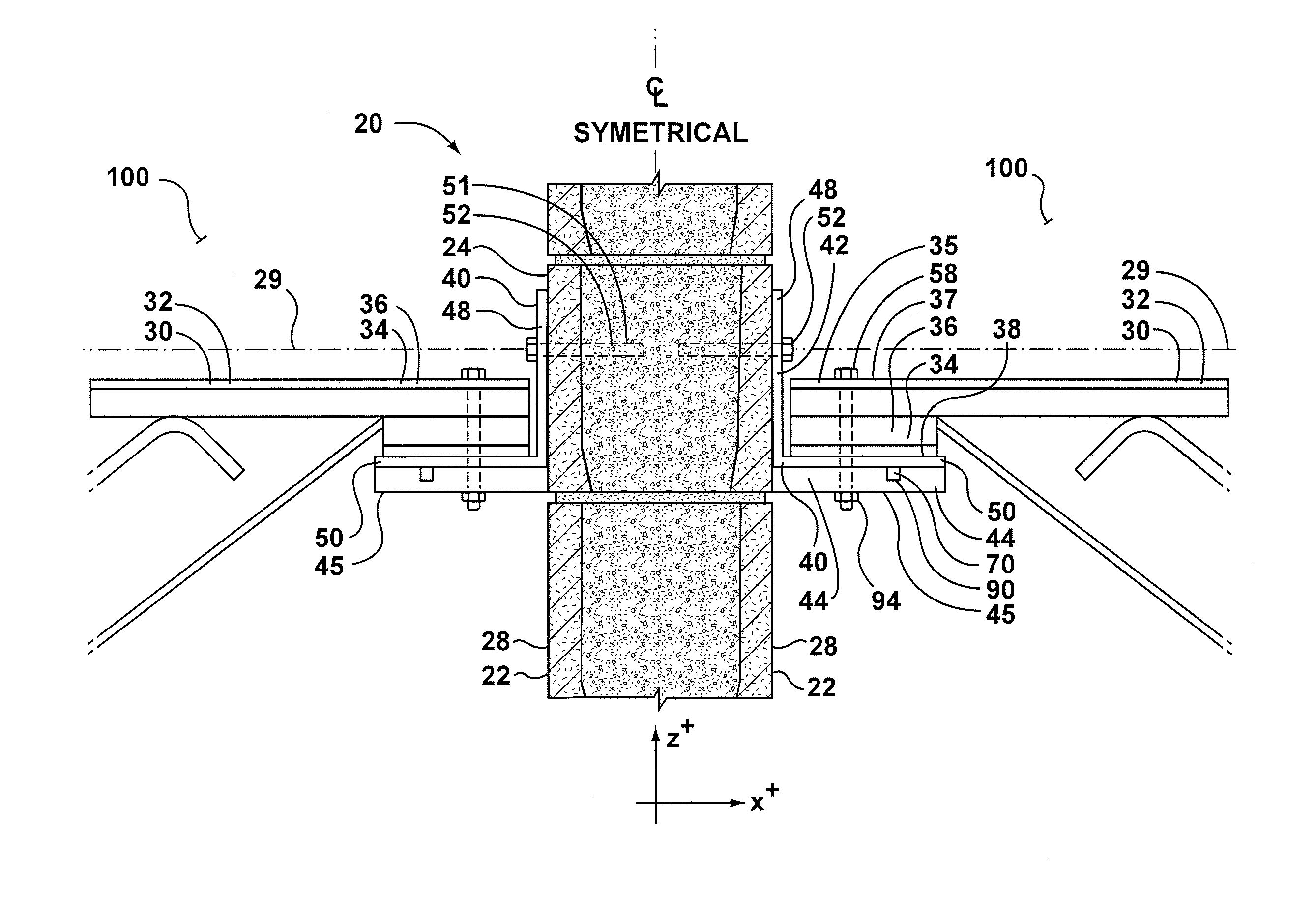
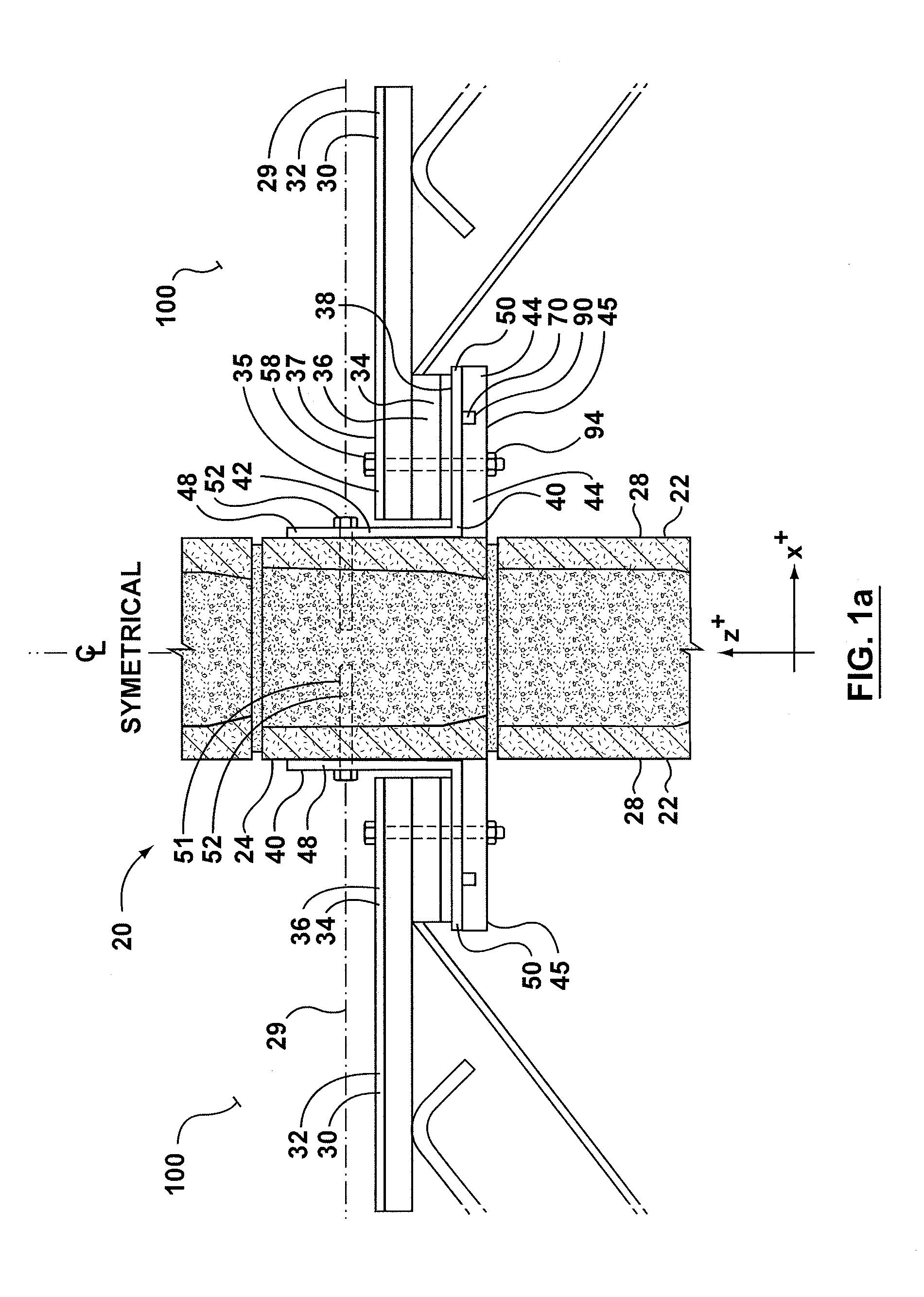
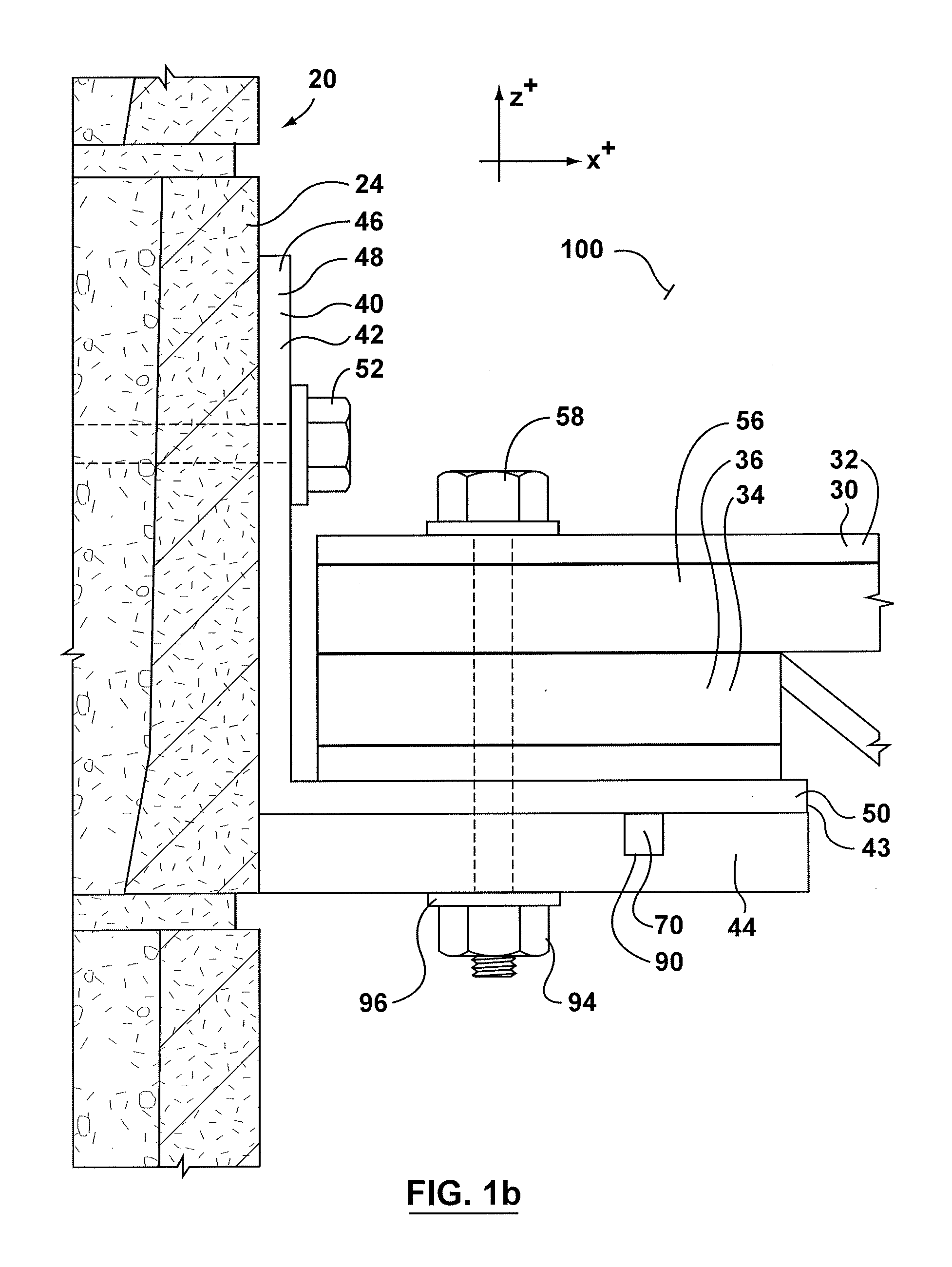
[0056]The description that follows, and the embodiments described therein, are provided by way of illustration of an example, or examples, of particular embodiments of the principles of the present invention. These examples are provided for the purposes of explanation, and not of limitation, of those principles and of the invention. In the description, like parts are marked throughout the specification and the drawings with the same respective reference numerals. The drawings may be taken as being to scale, or generally proportionate, unless indicated otherwise.

[0057]The scope of the invention herein is defined by the claims. Though the claims are supported by the description, they are not limited to any particular example or embodiment, and any claim may encompass processes or apparatuses other than the specific examples described below. Other than as indicated in the claims themselves, the claims are not limited to apparatuses or processes having all of the features of any one app...


PUM


Abstract

The end of a beam is joined to a wall structure by a self-releasing structural assembly. The self-releasing structural assembly has a first portion that is anchored to the wall. A second portion sticks out from the wall. This portion is fireproof and non-thermally degradable. It defines a seat for receiving the beam end. The assembly also includes a thermally degradable member mounted to the second portion. In normal use the beam fasteners squeeze the end of the beam, the support bracket seat, and the consumable, thermally degradable member in compression. When exposed to heat or flame the consumable, thermally degradable member softens, releasing the compression in the structural sandwich of parts. The end of the beam is then able to translate away from the wall structure. The consumable member can be inspected, replaced if necessary, and the beam fasteners re-tensioned, without removing the beam end from the seat.

Description

CROSS-REFERENCE TO RELATED APPLICATIONS[0001]This application is a continuation-in-part of U.S. patent application Ser. No. 13 / 098,908, filed May 2, 2011, the content of which is incorporated herein by reference. This application is also a continuation-in-part of U.S. patent application Ser. No. 13 / 227,915, filed Sep. 8, 2011, which claims priority to U.S. Provisional Patent Application No. 61 / 381,205, filed Sep. 9, 2010, the contents of which are incorporated herein by reference.FIELD OF INVENTION[0002]This Application relates to structural materials for use in the construction of buildings, and, in one particular context, to support structure for joists or other structural cross-members, and to use thereof.BACKGROUND OF THE INVENTION[0003]This specification relates to a break-away connector for connecting structural components, such as a floor or ceiling to a firewall, and to a method of constructing a firewall connection system.[0004]In residential, commercial and industrial buil...

Claims


Application Information

Patent Timeline
IPC IPC(8): E04B1/94
CPCE04B1/94
Inventor HATZINIKOLAS, MICHAEL
Owner HATZINIKOLAS MICHAEL
Why Eureka
Try Eureka