Charge control device for vehicle

Active Publication Date: 2013-06-13
NISSAN MOTOR CO LTD
View PDF3 Cites 16 Cited by
  • Summary
  • Abstract
  • Description
  • Claims
  • Application Information

AI Technical Summary

Benefits of technology

[0007]Hence, even when a charge power drop occurs due to the concurrency of the timed charge and the heating of the battery, it is possible to appropriately extend the charge time duration by virtue of the delayed charge suspension time, thus

Problems solved by technology

Thus, this leads to a pr

Method used


Image

  • Charge control device for vehicle
  • Charge control device for vehicle
  • Charge control device for vehicle

Examples


first embodiment

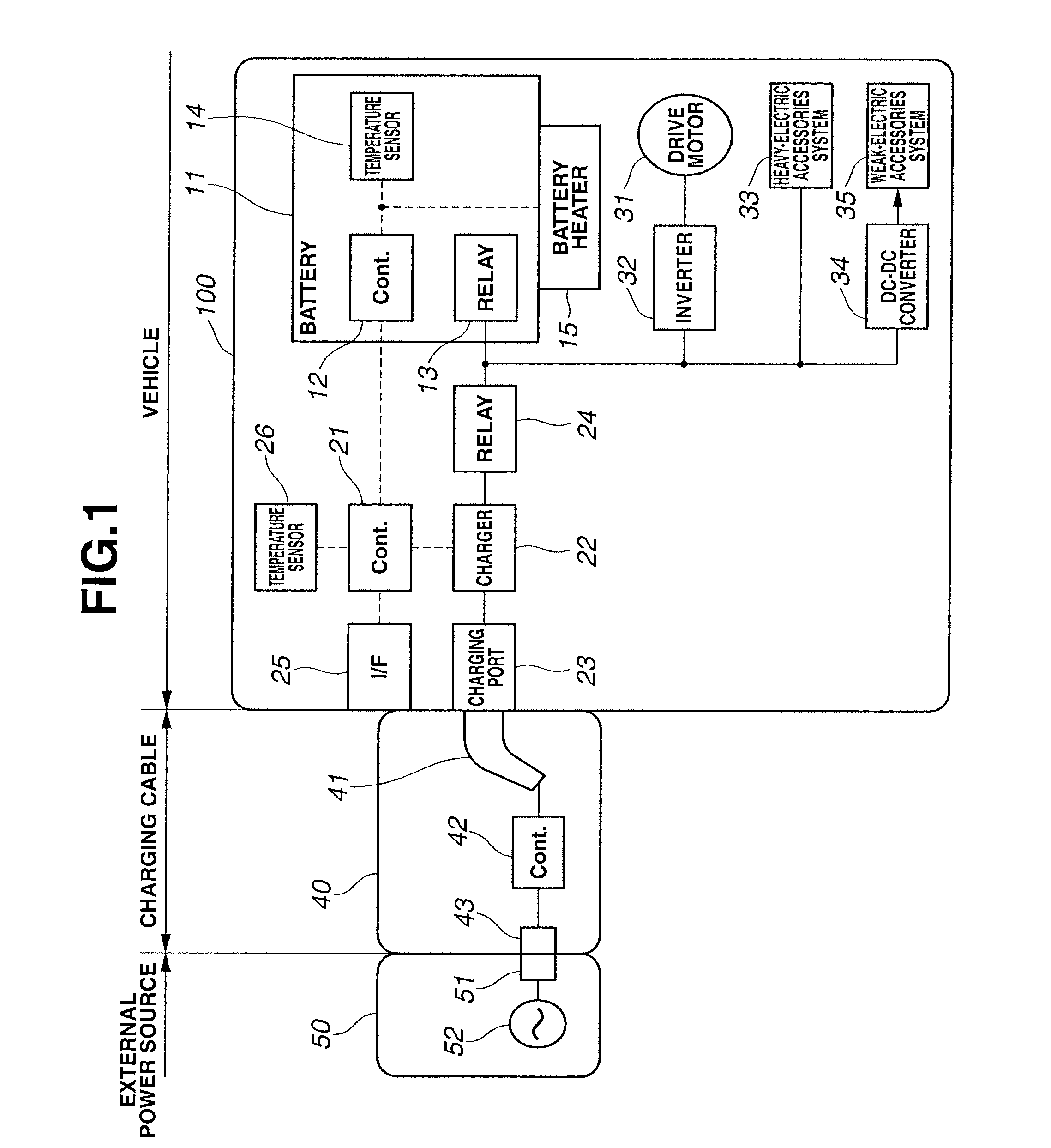
[0013]FIG. 1 is the system diagram illustrating a charge control device for a vehicle of the first embodiment. The vehicle of the first embodiment is an electric vehicle, which can run, using only a battery as energy. An electrically-driven vehicle 100 has a chargeable / dischargeable battery 11. A direct-current (DC) power, stored in the battery 11, is converted into an alternating-current (AC) power by means of an inverter 32. The converted power is supplied to a drive motor 31 to drive the vehicle. By connecting the electrically-driven vehicle 100 to an external power source 50 via a charging cable 40, battery 11 receives electric power from the external power source such that the battery is recharged. Regarding the sort of external power source 50, generally, in the case of normal charge, a commercial power supply is used. In the case of quick charge, a quick charger is used. FIG. 1 shows a normal-charge form. Electric power of a commercial power supply 52 can be fed by a power re...


PUM


Abstract

A charge control device is configured to delay a charge suspension time if a battery is being heated by a battery heater when carrying out a timed charge in a charge time slot specified by a user via an interface device. This enables the battery to be charged to a target charge amount without increasing a required capacity of the battery heater.

Description

TECHNICAL FIELD[0001]The present invention relates to a charge control device for a vehicle that can run, using electric power of a battery.BACKGROUND ART[0002]A technology, by which a charge control of a battery is performed in a vehicle that can run, using electric power of the battery, has been disclosed in Patent document 1. This patent official gazette teaches that the battery is pre-heated by a heater before a charge initiation time specified beforehand such that the battery charging can be completed within a given time duration, when it has been determined that the battery charging cannot be completed within the given time duration by a charge time duration lengthened due to a temperature fall in the battery.[0003]However, in order for the heating of the battery to be completed before the charge initiation time, the battery has to be heated up to a predetermined battery temperature for a short time. For instance, when heating a large capacity of battery, which battery is used...

Claims


Application Information

Patent Timeline
IPC IPC(8): B60L11/18H01M10/44H01M10/60H01M10/615H01M10/625H01M10/633H01M10/6571H02J7/00H02J7/04
CPCH02J7/0068Y02T10/7291H01M10/443H01M10/486H01M10/5006H01M10/502H01M10/5093B60L11/1809Y02T10/7005Y02T10/705Y02T90/16Y02T10/7216Y02T90/14Y02T90/127B60L1/02B60L11/1803B60L11/1816B60L11/1875B60L2210/10B60L2240/545B60L2240/662H02J7/0073H01M10/63H01M10/615H01M10/66Y02T10/7072B60L53/14B60L50/51B60L58/27H02J7/0071Y02T10/72Y02T10/70Y02E60/10H02J7/04H01M10/44Y02T90/12
Inventor YAMAMOTO, NAOKIOKINO, KAZUHIKO
Owner NISSAN MOTOR CO LTD
Why Eureka
Try Eureka