Image display device and stereo image display system

Inactive Publication Date: 2012-08-02
SHARP KK
View PDF0 Cites 24 Cited by
  • Summary
  • Abstract
  • Description
  • Claims
  • Application Information

AI Technical Summary

Benefits of technology

[0010]According to the present invention, an image display device that achieves stereo image display with the help of a vision aid and that allows a person seeing the screen without such a vision aid to view a less strange image, and a stereo image display system including such an image display are provided.

Problems solved by technology

However, one problem with glasses-based stereo image display systems is that, if a person without special glasses for these systems views the screen, he sees left and right eye images superimposed on each other.

Method used


Image

  • Image display device and stereo image display system
  • Image display device and stereo image display system
  • Image display device and stereo image display system

Examples


first embodiment

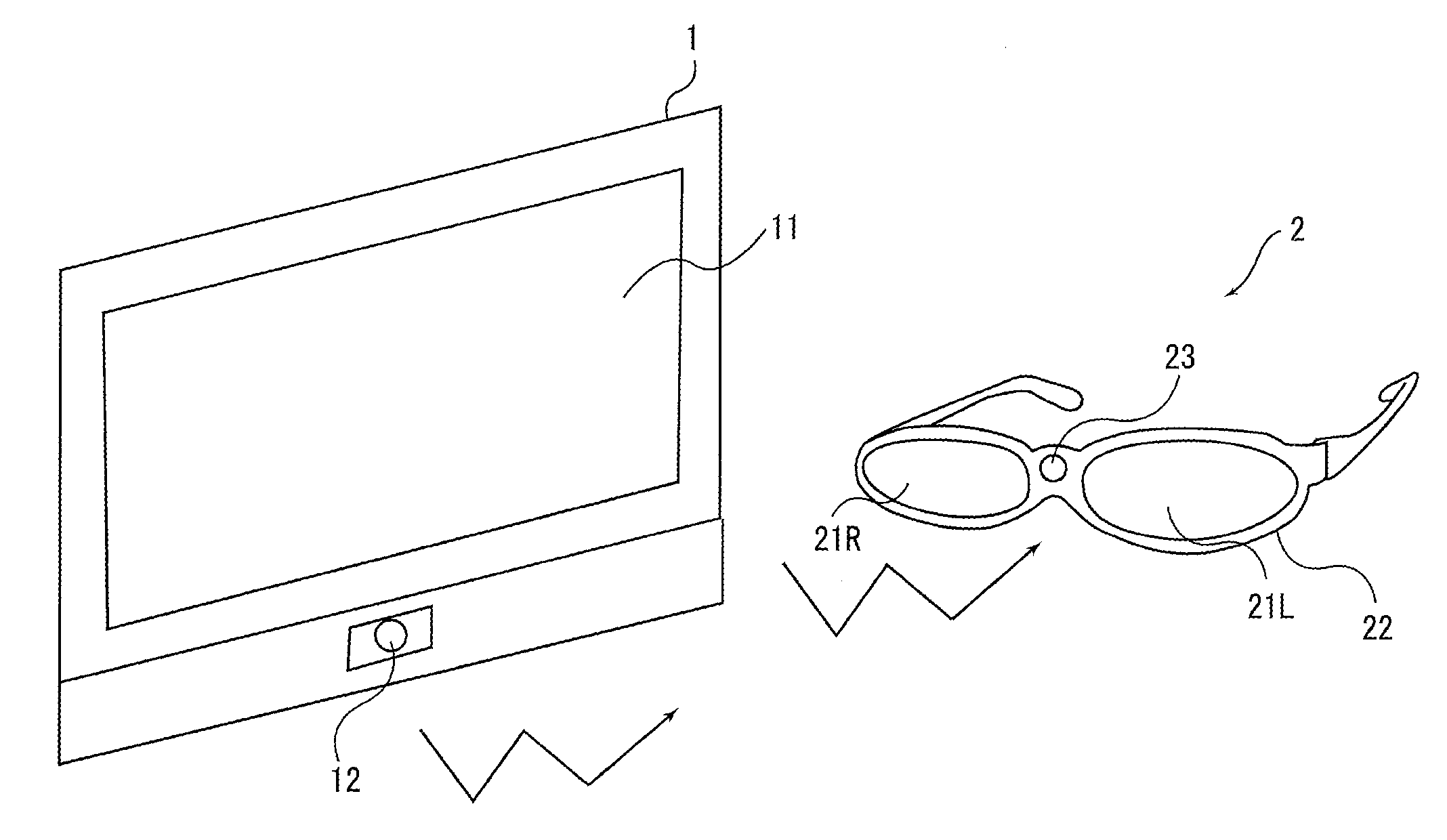
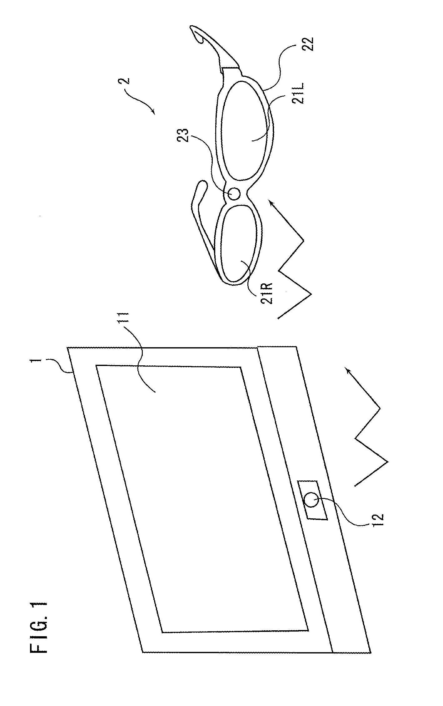
[0046]The first embodiment of the present invention will be described below. FIG. 1 is a schematic view of an entire stereo image display system according to a first embodiment. As shown in FIG. 1, the stereo image display system according to the first embodiment includes an image display device 1 and a pair of shutter glasses, or a vision aid, 2.

[0047]In the present embodiment, the image display device 1 is a liquid crystal display. However, the image display device 1 is not limited to a liquid crystal display and may be any light emitting display or a non-light emitting display. Examples of light emitting displays include, but are not limited to, cathode ray tubes, plasma displays, organic electroluminescent devices, inorganic electroluminescent devices and field emission displays. Examples of non-light emitting displays include, but are not limited to, liquid crystal displays mentioned above as well as rear projection devices.

[0048]The image display device 1 includes a display mo...

second embodiment

[0085]A second embodiment of the present invention will be described below. The components with the similar functions as those of the above embodiment are labeled with the same reference characters as in the above embodiment and their detailed description will be omitted. This applies to the other embodiments below.

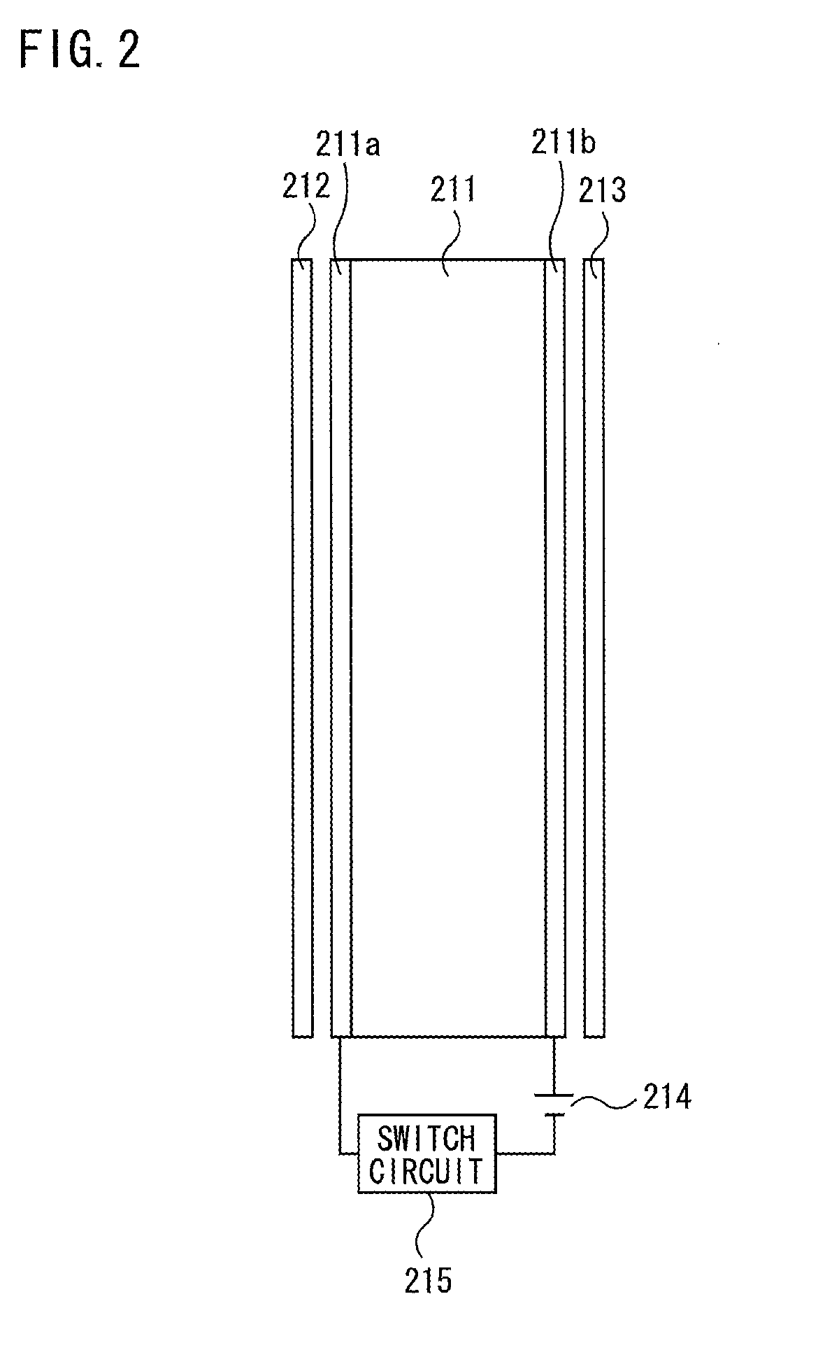
[0086]In the first embodiment, the shutter glasses 2 provided light blocking and light passing by controlling the liquid crystal shutters 21L and 21R such that each of the shutters is either completely open or completely closed. In contrast, in the second embodiment, the 2D / 3D dual purpose mode sets a voltage applied to the liquid crystal cell 211 such that it passes only a portion, not all, of the light that has passed through the polarizer 212 to the polarizer 213 when the liquid crystal cell 211 of the liquid crystal shutter 21L is open. Specifically, supposing the voltage applied when the liquid crystal shutter 21L passes no light is 0 volts and the voltage applied wh...

third embodiment

[0092]A third embodiment of the present embodiment will be described below. An image display device 1 according to the third embodiment alternately displays a left eye image and a right eye image with an equal maximum brightness, but generates left eye image display data and right eye image display data such that the number of pixels contributing to the display of a right eye image is smaller than the number of pixels contributing to the display of a left eye image when the 2D / 3D dual purpose mode is selected. Thus, in the image display device 1 according to the third embodiment, the image processor 132 in the video processor 13 described in connection with the first embodiment is replaced by an image processor 135 that performs different processes, as shown in FIG. 7. In the present embodiment, the image processor 135 and the display data generator 133 function as an average brightness controller.

[0093]The image processor 135 receives mode switching data 61 and pixel mapping patter...


PUM


Abstract

An image display device that provides stereo image display with the help of special glasses (i.e. a vision aid) and that allows a viewer looking at the screen without such a vision aid to view a less strange image, and a stereo image display system including such an image display device are provided. The image display device includes: a display module capable of displaying a left eye image (L) to be viewed via a left eye portion of the vision aid and a right eye image (R) to be viewed via a right eye portion of the vision aid, the left eye and right eye images being displayed separately in time and space; and an average brightness controller capable of regulating an average brightness of the left eye image and an average brightness of the right eye image displayed on the display module in one given frame such that these average brightnesses are different from each other.

Description

TECHNICAL FIELD[0001]The present invention relates to an image display device which, in combination with a vision aid, allows a viewer to view a stereo image, and a stereo image display system including the image display device and the vision aid.BACKGROUND ART[0002]In recent years, increasingly active research and development efforts have been made to put into practical use stereo image display systems that allow a viewer to view a stereoscopic image.[0003]Conventional stereo image display systems are generally classified into: (1) so-called glasses-based stereo image display systems, where right and left eye images with a parallax are displayed on an image display device and special glasses (i.e. a vision aid), worn by a viewer, allow the viewer to view only left eye images with his left eye and to view only right eye images with his right eye; and (2) so-called naked-eye stereo image display systems, which allow the viewer to view a stereo image without special glasses.[0004]Glas...

Claims


Application Information

Patent Timeline
Patent Type & Authority Applications(United States)
IPC IPC(8): H04N13/04G02B30/25
CPCG02B27/2264G02B27/26G03B35/18G09G5/10H04N13/0438H04N13/0454G09G3/003H04N13/0434G02B30/24G02B30/25H04N13/337H04N13/341H04N13/359
Inventor NAKAMURA, TATSUNORIKUMAKURA, TAKESHISHIOMI, MAKOTO
Owner SHARP KK
Why Eureka
Try Eureka