
High-voltage regulated power supply

a high-voltage regulated, power supply technology, applied in the direction of dc-dc conversion, power conversion systems, instruments, etc., can solve the problems of difficult to regulate the output voltage of a voltage multiplier, the step-up transformer is likely to be a costly custom component, and the step-up transformer is generally large and heavy. achieve the effect of low dropou

Active Publication Date: 2012-08-02
APPLE INC
View PDF6 Cites 9 Cited by
  • Summary
  • Abstract
  • Description
  • Claims
  • Application Information

AI Technical Summary

Benefits of technology

[0007]The disclosed embodiments relate to a method for generating high-voltage DC power from AC line power using a power-supply circuit. This power-supply circuit includes a voltage multiplier and a low dropout (LDO) regulator, and does not include a step-up transformer. Conventional power supplies often use a custom step-up transformer, which is expensive unless the power supplies are manufactured in high quantities. In contrast, one embodiment of the present disclosure provides a solid-state implementation of a 700 V regulated power supply that can take up to a 1020 V input from a six-times voltage multiplier powered from the AC mains. Hence, the disclosed power-supply circuit eliminates the need for large, heavy and expensive step-up transformers and chokes that are used in conventional high-voltage DC power supplies.

Problems solved by technology

However, in order to operate effectively at the line frequency, the step-up transformer generally needs to be large and heavy.
Furthermore, the step-up transformer is likely to be an expensive custom component, because such step-up transformers are not widely used.
Conventional power supplies often use a custom step-up transformer, which is expensive unless the power supplies are manufactured in high quantities.
Note that, designs for stand-alone voltage multipliers and LDO regulators are fairly well known, it can be quite challenging to regulate the output voltage of a voltage multiplier.
Moreover, existing LDO regulator designs are not configured to operate at high voltages and power levels.

Method used


Image

  • High-voltage regulated power supply
  • High-voltage regulated power supply
  • High-voltage regulated power supply

Examples


Embodiment Construction

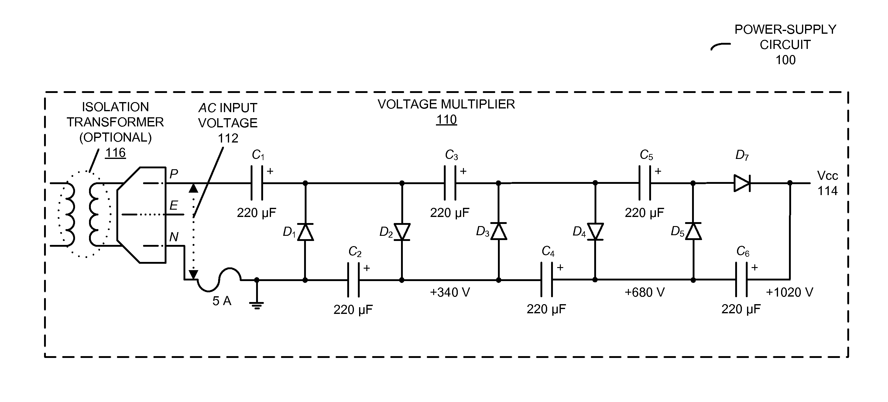
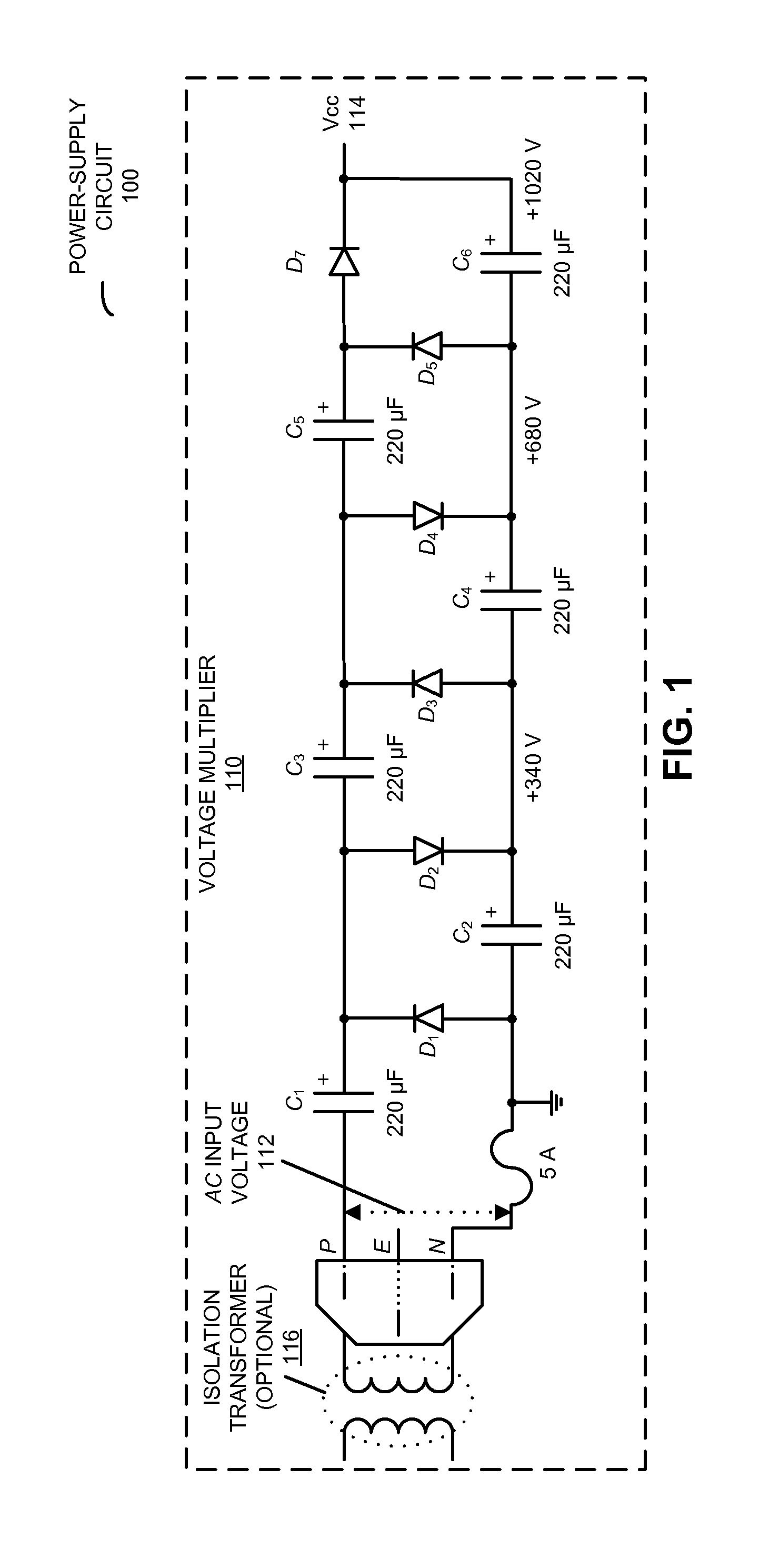
[0015]Instead of using a custom step-up transformer to increase the voltage, the power-supply circuit in the present disclosure feeds AC power through a three-stage, half-wave Cockcroft-Walton multiplier which bumps the line voltage up above 1 kV (for example, to 1020 V). This is shown in FIG. 1, which presents a block diagram illustrating a voltage multiplier 110 (in this example, a Cockcroft-Walton multiplier) in power-supply circuit 100.

[0016]The Cockcroft-Walton multiplier uses only capacitors and diodes to produce a rectified and filtered output voltage Vcc 114, which is a multiple of the peak AC input voltage 112. In particular, when the voltages on capacitors C1, C3 and C5 on the top of voltage multiplier 110 (which are charged by the AC line voltage) exceed the voltage thresholds of the diodes (which act as unidirectional switches), charge flows into (and is held by) C2, C4 and C6 on the bottom of voltage multiplier 110. Thus, C1, C3 and C5 dump charge into C2, C4 and C6, an...


PUM


Abstract

The disclosed embodiments relate to a power-supply circuit, an electronic device that includes the power-supply circuit, and a method for generating high-voltage DC power from AC line power using the power-supply circuit. This power-supply circuit includes a voltage multiplier and a low dropout (LDO) regulator, and does not include a step-up transformer. Conventional power supplies often use a custom step-up transformer, which is expensive unless the power supplies are manufactured in high quantities. In contrast, one embodiment of the present disclosure provides a solid-state implementation of a 700 V regulated power supply that can take up to a 1020 V input from an 6× voltage multiplier powered from the AC mains. Hence, the disclosed power-supply circuit eliminates the need for large, heavy and expensive step-up transformers and chokes that are used in conventional high-voltage DC power supplies.

Description

CROSS REFERENCE TO RELATED APPLICATION[0001]This application claims priority under 35 U.S.C. §119(e) to U.S. Provisional Patent Application Ser. No. 61 / 436,891, entitled “High Voltage DC Power Supply Using Voltage Multiplier with Feedback Regulation,” by Eric Smith, P. Jeffrey Ungar and Heather Sullens, filed on Jan. 27, 2011, having attorney docket number APL-P10764USP1, the contents of which are herein incorporated by reference.BACKGROUND[0002]1. Field[0003]The disclosed embodiments generally relate to power supplies. More specifically, the disclosed embodiments relate to the design of a high-voltage DC power supply, which is powered by an AC line, and which operates without using a step-up transformer.[0004]2. Related Art[0005]High-voltage DC power supplies that provide moderate power output are commonly used in a number of applications, such as: lasers, photographic flash units, displays and audio tube amplifiers. These high-voltage power supplies typically step up the AC line v...

Claims


Application Information

Patent Timeline
IPC IPC(8): H02M7/10
CPCH02M7/10
Inventor SMITH, ERICUNGAR, P. JEFFREYSULLENS, HEATHER R.
Owner APPLE INC
Learn More