
Lubricant Supplying Device, Process Cartridge, And Image Forming Apparatus

a technology of lubricant supply device and process cartridge, which is applied in the field of electrographic image forming apparatus, can solve the problems of defective assembly of compressing spring, cleaning defect, and inability to display the original function of the lubricant supply devi

Active Publication Date: 2012-08-02
RICOH KK
View PDF27 Cites 9 Cited by
  • Summary
  • Abstract
  • Description
  • Claims
  • Application Information

AI Technical Summary

Benefits of technology

[0010]It is an object of the present invention to at least partially solve the problems in the conventional technology, by providing a lubricant supplying device, a process cartridge, and an image forming apparatus in which an assembly defect of a compressing spring used to bias a solid lubricant in the press-contact direction scarcely occurs.
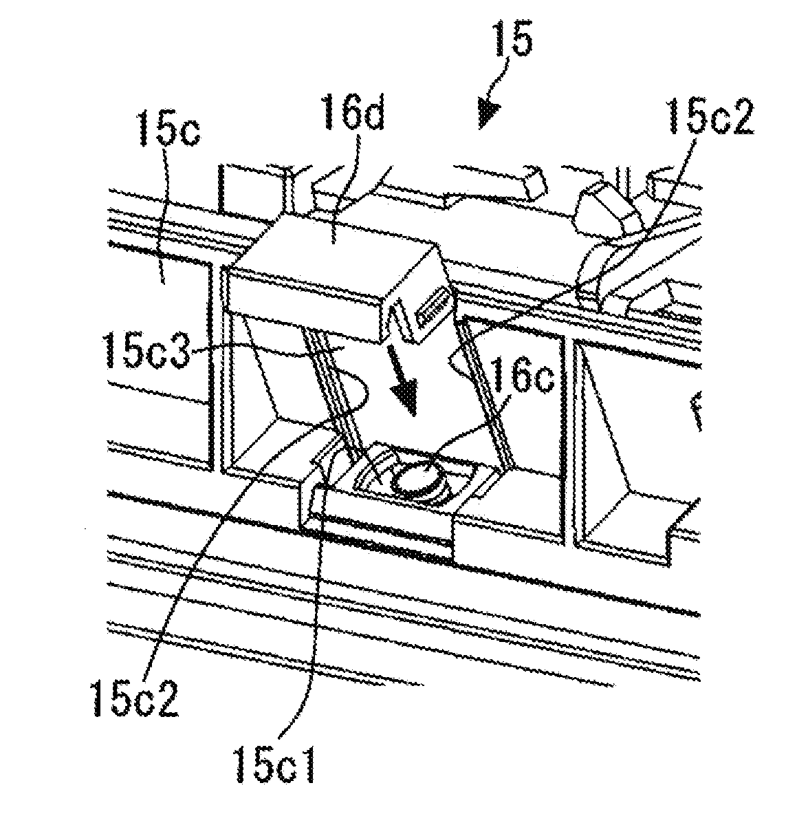
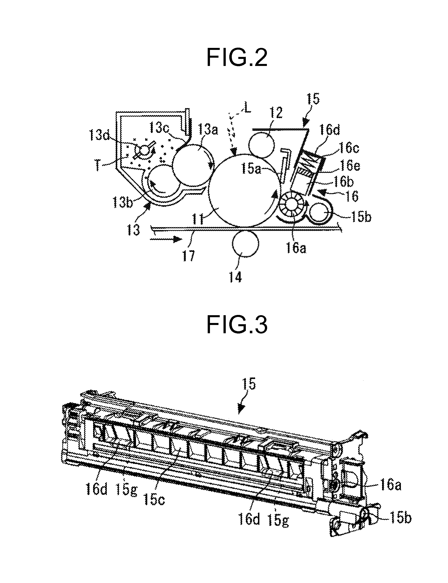
[0011]In order to solve the aforementioned problems, a lubricant supplying device that supplies a lubricant to an image carrier that carries a toner image according to one aspect of the present invention is constructed in such a manner as to include: a lubricant supplying roller that rotates in a predetermined direction and slides on the image carrier; a solid lubricant that slides on the lubricant supplying roller; a holding member that holds the solid lubricant; a compressing spring with one end being brought into contact with the holding member, thereby biasing the solid lubricant toward the lubricant supplying roller; and a casing that covers the outside of the device, wherein the casing includes an opening portion that allows the other end of the compressing spring, having the one end coming into contact with the holding member, to be exposed therethrough, and a cover member that is installed in the opening portion in a removable manner so that the cover member comes into contact with the other end of the compressing spring and determines a biasing force of the compressing spring.

Problems solved by technology

However, in a case in which a contact portion of the cleaning blade is chipped (damaged) due to the friction against the photosensitive drum, the non-transferred toner goes through a gap between the damaged cleaning blade and the photosensitive drum, which results in a cleaning defect.
In the lubricant supplying device of the related arts, since the compressing springs which are used to bias the solid lubricant in the press-contact direction are attached to the casing in a manner that the compressing springs may not be seen between the holding member and the casing, the compressing springs are attached to the casing in a buckled state or the compressing springs slip off the casing, which easily results in the defective assembly of the compressing springs.
Then, when such problems arise, the original function of the lubricant supplying device may not be exhibited.

Method used


Image

  • Lubricant Supplying Device, Process Cartridge, And Image Forming Apparatus
  • Lubricant Supplying Device, Process Cartridge, And Image Forming Apparatus
  • Lubricant Supplying Device, Process Cartridge, And Image Forming Apparatus

Examples


embodiment

[0027]Hereinafter, an embodiment of the invention will be described in detail with reference to the drawings. Furthermore, in the respective drawings, the same reference signs are given to the same or equivalent constituents, and the repetitive description thereof will be appropriately simplified or will not be repeated.

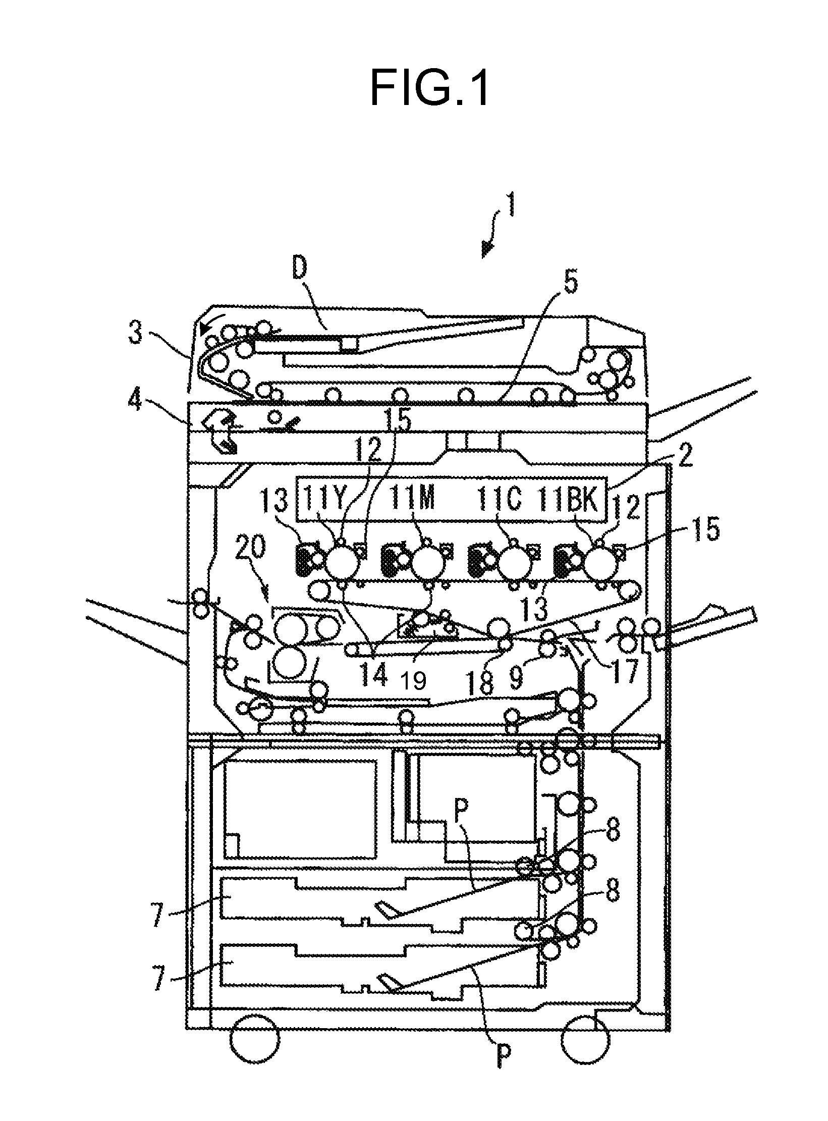
[0028]First, in FIG. 1, the entire configuration and the entire operation of an image forming apparatus will be described.

[0029]In FIG. 1, an apparatus main body 1 of a tandem type color copying machine which serves as an image forming apparatus is illustrated, wherein reference numeral 2 denotes a writing unit which emits a laser beam based on input image information, numeral 3 denotes a document conveying unit which conveys a document D to a document reading unit 4, 4 denotes a document reading unit which reads the image information of the document D, 7 denotes a paper feeding unit which accommodates a recording medium P such as transfer paper, 9 denotes a registra...


PUM


Abstract

A lubricant supplying device includes a compressing spring that has one end coming into contact with a holding member in order to bias a solid lubricant toward a lubricant supplying roller and a casing that covers the outside of the device. Then, the casing includes an opening portion that allows the other end of the compressing spring, having the one end coming into contact with the holding member, to be exposed therethrough, and the casing further includes a cover member that is installed in the opening portion in a removable manner so that the cover member comes into contact with the other end of the compressing spring.

Description

CROSS-REFERENCE TO RELATED APPLICATIONS[0001]The present application claims priority to and incorporates by reference the entire contents of Japanese Patent Application No. 2011-014799 filed in Japan on Jan. 27 2011.BACKGROUND OF THE INVENTION[0002]1. Field of the Invention[0003]The present invention relates to an electro-photographic image forming apparatus such as a copying machine, a printer, a facsimile, or a multi-functional peripheral thereof, to a lubricant supplying device installed therein, and also to a process cartridge.[0004]2. Description of the Related Art[0005]Hitherto, in an image forming apparatus such as a copying machine or a printer, there is a known technique using a lubricant supplying device which supplies a lubricant to an image carrier such as a photosensitive drum or an intermediate transfer belt (for example, see Japanese Patent Application Laid-open No. 2006-201565 and Japanese Patent Application Laid-open No. 2001-305907).[0006]Specifically, non-transfer...

Claims


Application Information

Patent Timeline
IPC IPC(8): G03G21/00
CPCG03G21/0094
Inventor KARASAWA, SHINYAAMEMIYA, KENOKAMOTO, MICHIYAIWASAKI, TAKUMAAZEYANAGI, YUTA
Owner RICOH KK
Learn More