Communication device

Active Publication Date: 2012-08-02
BROTHER KOGYO KK
View PDF20 Cites 4 Cited by
  • Summary
  • Abstract
  • Description
  • Claims
  • Application Information

AI Technical Summary

Benefits of technology

[0004]However, in a case where the sending buffer and the receiving buffer have the same storage capacity, the sending buffer and the receiving buffer may not be utilized efficiently, and consequentl

Problems solved by technology

However, in a case where the sending buffer and the receiving buffer have the same storage capacity, the sending buffer and the receiving buffer

Method used


Image

  • Communication device
  • Communication device
  • Communication device

Examples


Example

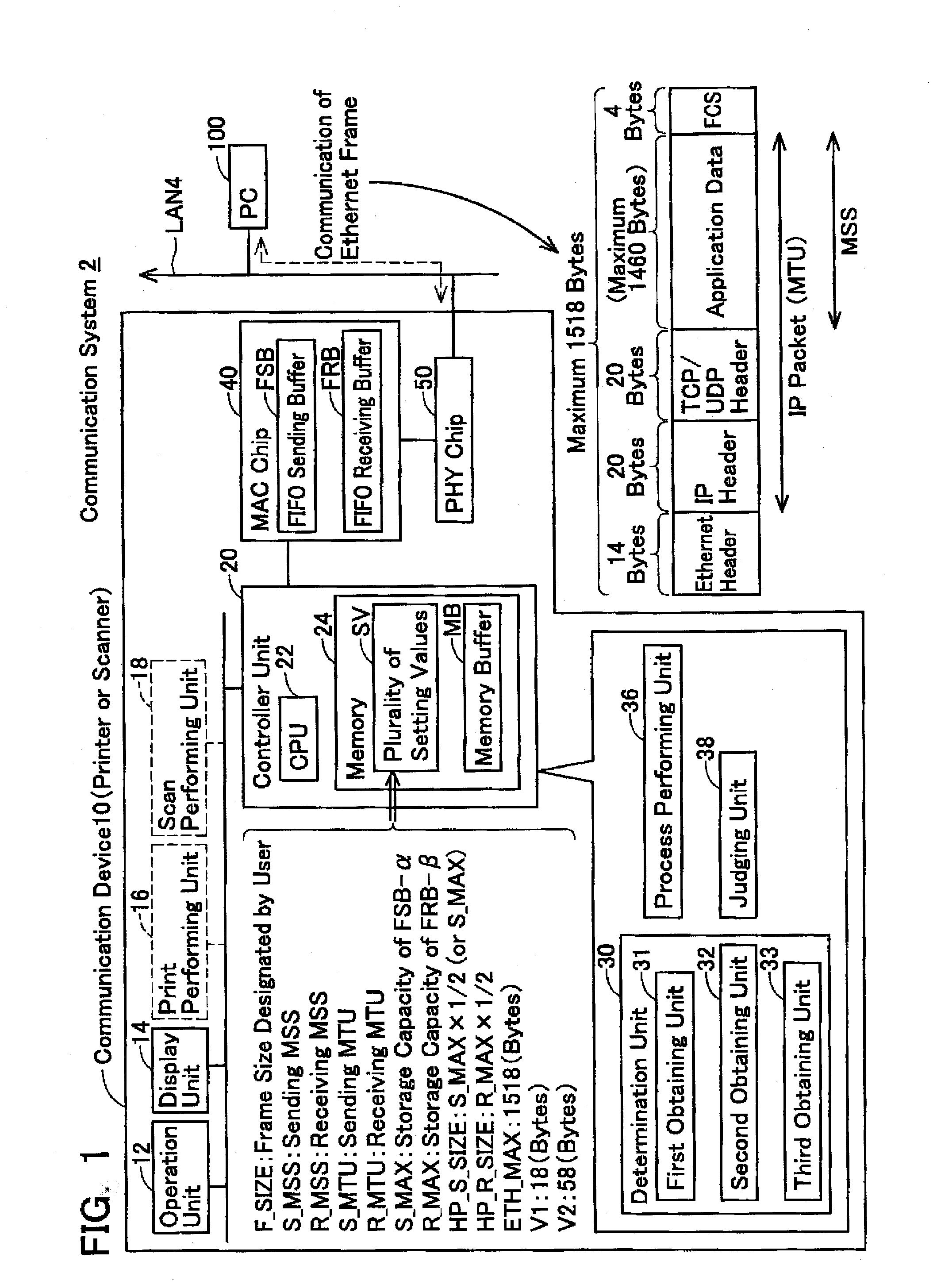
[0062]HP_S_SIZE and HP_R_SIZE shown in FIG. 1 will be described in detail in a third embodiment (to be described). Moreover, the S_MAX, R_MAX, ETH_MAX, V1, V2 are stored in advance in the memory 24 at the shipping stage of the communication device 10. The F_SIZE is stored in the memory 24 in S50 of FIG. 4 (to be described). Further, the four setting values S_MSS, R_MSS, S_MTU and R_MTU are stored in the memory 24 in S56 or S58 of FIG. 4 (to be described).

[0063](Storage Capacity of Two Buffers FSB, FRB)

[0064]As described above, the communication device 10 of the present embodiment corresponds to the gigabit Ethernet that is capable of realizing a high communication speed. In order to further increase the efficiency of communication using the gigabit Ethernet, the communication device 10 uses the jumbo frame. Thus, in case the jumbo frame is used, the size of the data included in one frame increases, and consequently the storage capacity of the FIFO buffer must be increased.

[0065]In a...

Example

FIRST SPECIFIC EXAMPLE

(In Case of Printer) (FIG. 7))

[0120]As described above, in case the communication device 10 is a printer, the relationship R_MAX>S_MAX is satisfied and, further, the relationship R_MAX≧F_SIZE is satisfied (see S50 of FIG. 4). As shown in FIG. 7, the determination unit 30 determines the S_MTU and S_MSS based on the relationship of the S_MAX, R_MAX and F_SIZE (i.e., S_MAX≧F_SIZE or R_MAX≧F_SIZE>S_MAX).

[0121]On the other hand, the determination unit 30 determines the R_MTU and R_MSS regardless of the relationship of the S_MAX, R_MAX and F_SIZE. Specifically, the determination unit 30 determines the values obtained utilizing the F_SIZE, i.e., F_SIZE-V1 and F_SIZE-V2, as the R_MTU and R_MSS respectively.

[0122]In case S_MAX≧F_SIZE, the determination unit 30 determines a value (F_SIZE-V1) obtained utilizing the F_SIZE as the S_MTU and R_MTU. Further, in case S_MAX≧F_SIZE, the determination unit 30 determines a value (F_SIZE-V2) obtained utilizing the F_SIZE as the S_...

Example

SECOND SPECIFIC EXAMPLE

(In Case of Scanner) (FIG. 8))

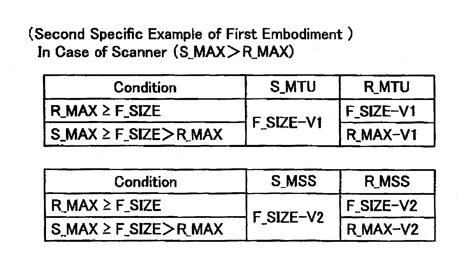
[0127]As described above, in case the communication device 10 is a scanner, the relationship S_MAX>R_MAX is satisfied and, further, the relationship S_MAX≧F_SIZE is satisfied (see S50 of FIG. 4). As shown in FIG. 8, the determination unit 30 determines the R_MTU and R_MSS based on the relationship of the S_MAX, R_MAX and F_SIZE (i e , R_MAX≧F_SIZE or S_MAX≧F_SIZE>R_MAX).

[0128]On the other hand, the determination unit 30 determines the S_MTU and S_MSS regardless of the relationship of the S_MAX, R_MAX and F_SIZE Specifically, the determination unit 30 determines the values obtained utilizing the F_SIZE, i.e., F_SIZE-V1 and F_SIZE-V2, as the S_MTU, S_MSS respectively.

[0129]In case R_MAX≧F_SIZE, the determination unit 30 determines a value (F_SIZE-V1) obtained utilizing the F_SIZE as the S_MTU, R_MTU. Further, in case S_MAX≧F_SIZE, the determination unit 30 determines a value (F_SIZE-V2) obtained utilizing the F_SIZE as the S_MSS an...


PUM


Abstract

A communication device may comprise a sending buffer having a first storage capacity, and a receiving buffer having a second storage capacity which is different from the first storage capacity. The communication device may determine a sending maximum data size in accordance with the first storage capacity, and determine a receiving maximum data size in accordance with the second storage capacity. The sending maximum data size and the receiving maximum data size may have different values. The communication device may perform a sending process for a sending frame of a sending target by utilizing the sending maximum data size, and perform a receiving process for a receiving frame of a receiving target by utilizing the receiving maximum data size.

Description

CROSS-REFERENCE TO RELATED APPLICATIONS[0001]This application claims priority to Japanese Patent Application No. 2011-019131, filed on Jan. 31, 2011, the contents of which are hereby incorporated by reference into the present application.TECHNICAL FIELD[0002]The technique taught in the present specification relates to a communication device to be connected with a network.DESCRIPTION OF RELATED ART[0003]A communication device usually comprises a sending buffer configured to store a sending frame to be sent to a network, and a receiving buffer configured to store a receiving frame received from the network. The sending buffer and the receiving buffer usually have the same storage capacity.SUMMARY[0004]However, in a case where the sending buffer and the receiving buffer have the same storage capacity, the sending buffer and the receiving buffer may not be utilized efficiently, and consequently a communication of data (i.e. sending and receiving of data) may not be performed efficiently...

Claims


Application Information

Patent Timeline
IPC IPC(8): G06F15/16H04L47/27H04L47/36
CPCH04L49/90
Inventor SAITO, KEN
Owner BROTHER KOGYO KK
Why Eureka
Try Eureka