
Method for performing a change of mode in devices directly communicating with each other in a wireless connection system, and apparatus for same

a wireless connection and mode change technology, applied in the field of wireless access systems, can solve problems such as study on the method of performing, and the method of performing a mode change, and achieve the effects of efficient communication, and poor link quality of the device to the device communication

Active Publication Date: 2016-03-15
LG ELECTRONICS INC
View PDF12 Cites 4 Cited by
  • Summary
  • Abstract
  • Description
  • Claims
  • Application Information

AI Technical Summary

Benefits of technology

The present invention allows D2D devices to communicate in a flexible way, whether it be with another D2D device or a cell phone. This means that data can be seamlessly transmitted / received even if the communication quality is poor. Additionally, if the communication quality is very poor, the D2D devices can easily switch to a cell phone to ensure smooth communication. Overall, the invention improves device-to-device communication and makes it more efficient.

Problems solved by technology

If many D2D devices communicate with a base station using the one-to-one communication scheme, a network overload may occur due to signaling with the base station.
As mentioned in the foregoing description, if the D2D communication is rapidly spread, overhead occurred by communication between D2D devices or communication between D2D devices and base station may cause a problem.
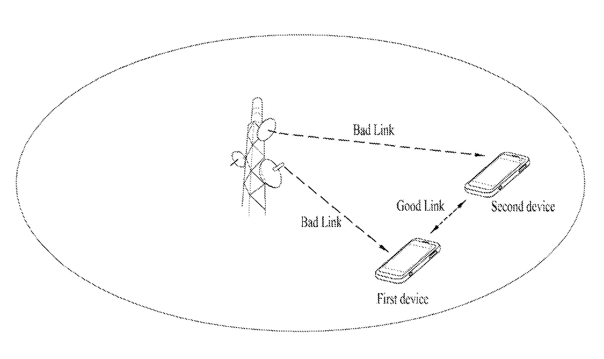
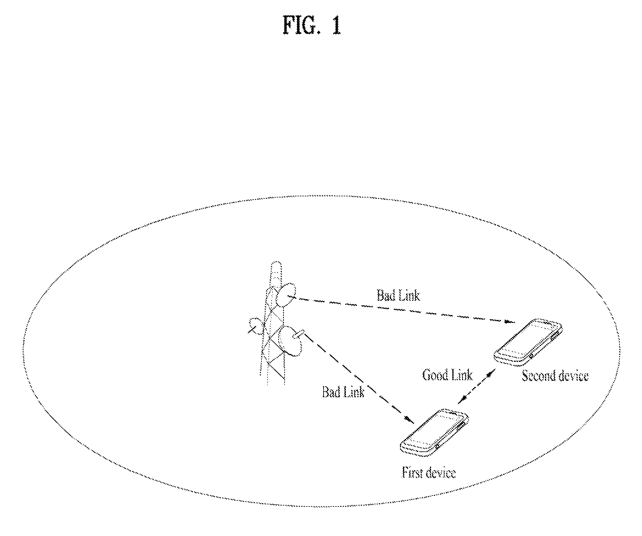
According to a related art, study on a method of performing a seamless communication in case of a poor D2D connection state and a method of performing a mode change (handover to a cellular network) while performing a direct communication between devices is not satisfactory.

Method used


Image

  • Method for performing a change of mode in devices directly communicating with each other in a wireless connection system, and apparatus for same
  • Method for performing a change of mode in devices directly communicating with each other in a wireless connection system, and apparatus for same
  • Method for performing a change of mode in devices directly communicating with each other in a wireless connection system, and apparatus for same

Examples


first embodiment

2. 2. 1. First Embodiment

[0106]FIG. 3 is a flowchart for an example of a method of making a handover to a relay device while performing a device to device communication according to one embodiment of the present invention.

[0107]Embodiment according to FIG. 3 shows examples of a case (2. 1. 1. 1.) that a neighboring device does not periodically disseminate a reference signal for measuring channel quality and a case (2. 1. 2. 1.) that a D2D device which has transmitted a reference signal request message preferentially measures channel quality.

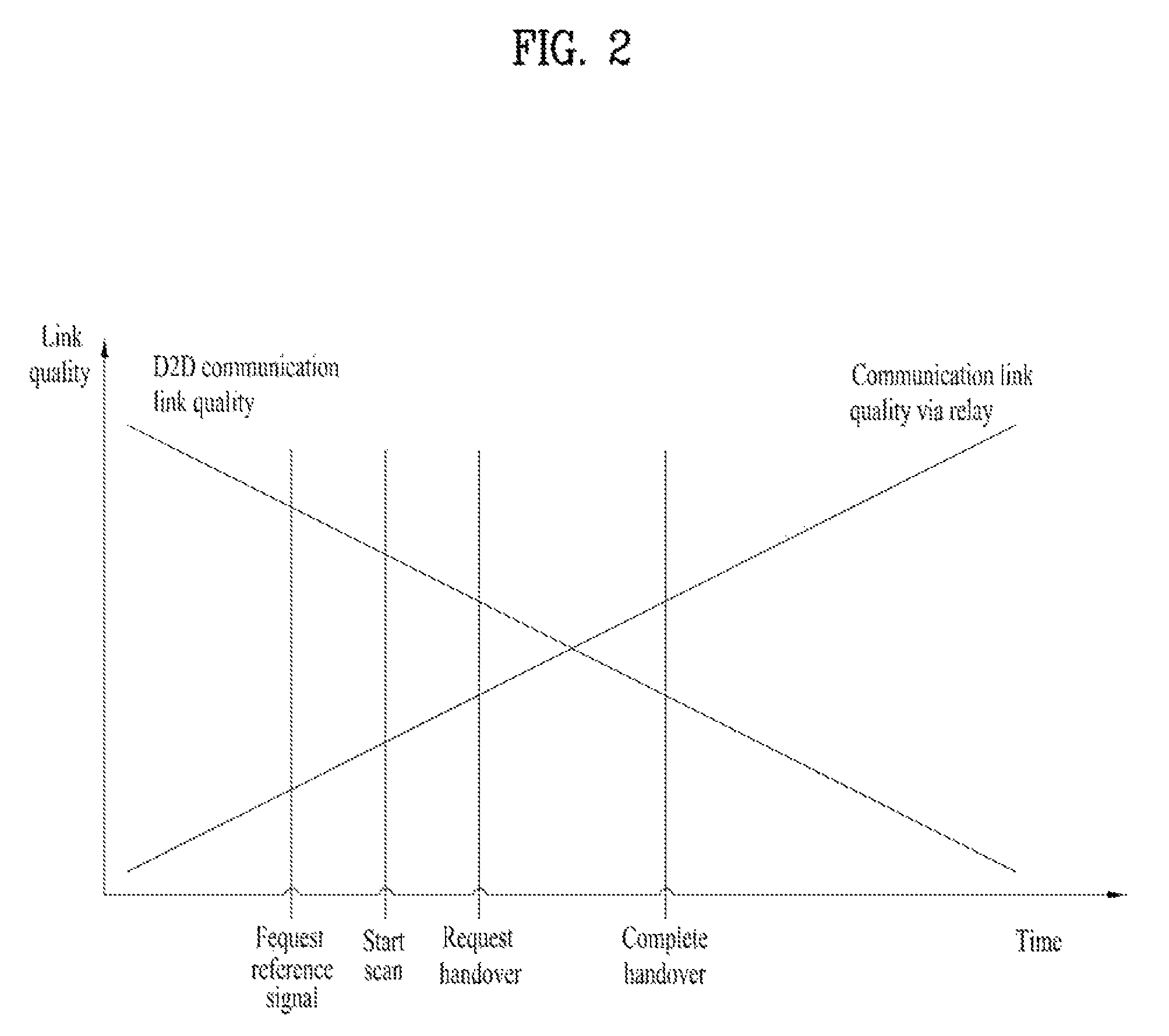
[0108]Referring to FIG. 3, if link quality of a D2D communication drops below a device search threshold, a first device performing the D2D communication with a second device perceives a handover state [S301]. In particular, if the link quality of the D2D communication drops below the device search threshold, the D2D device performing the D2D communication measures channel quality with a neighboring device and starts to search for a relay device.

[...

second embodiment

2. 2. 2. Second Embodiment

[0120]FIG. 4 is a flowchart for an example of a method of making a handover to a relay device while performing a device to device communication according to one embodiment of the present invention.

[0121]Embodiment according to FIG. 4 shows examples of a case (2. 1. 1. 2.) that a neighboring device periodically disseminate a reference signal for measuring channel quality and a case (2. 1. 2. 1.) that a D2D device which has transmitted a reference signal request message preferentially measures channel quality.

[0122]Referring to FIG. 4, if a D2D neighboring device periodically disseminates a reference signal for measuring channel quality, the S303 in FIG. 3 may be omitted. In particular, the first device may not transmit a reference signal request message for requesting a transmission of a reference signal with a broadcast scheme.

[0123]Since each step of the embodiment of FIG. 4 is identical to the each step of the embodiment of FIG. 3 except the S303, followi...

third embodiment

2. 2. 3. Third Embodiment

[0124]FIG. 5 is a flowchart for an example of a method of making a handover to a relay device while performing a device to device communication according to one embodiment of the present invention.

[0125]Embodiment according to FIG. 5 shows examples of a case (2. 1. 1. 1.) that a neighboring device does not periodically disseminate a reference signal for measuring channel quality and a case (2. 1. 2. 2.) that devices performing a D2D communication simultaneously measure channel quality.

[0126]Referring to FIG. 5, if link quality of a D2D communication drops below a device search threshold, a first device performing the D2D communication with a second device perceives a handover state [S501]. In particular, if the link quality of the D2D communication drops below the device search threshold, the D2D device performing the D2D communication measures channel quality with a neighboring device and starts to search for a relay device.

[0127]Subsequently, the first dev...


PUM


Abstract

The present invention relates to a method for determining whether a mode change condition for performing a hand-over to a cellular network through which devices communicate with each other is satisfied, transmitting a mode change instruction message to a base station when the mode change condition is satisfied, receiving a mode change command message for starting a mode change from the base station, transmitting a first data packet index with respect to a data packet transmitted to a second device at a final stage through the communication between the devices to the base station, ending the communication with the second device when the inter-device communication end request message is received from the base station, and transmitting data to the second device through the cellular network.

Description

CROSS-REFERENCE TO RELATED APPLICATIONS[0001]This application is the National Stage filing under 35 U.S.C. 371 of International Application No. PCT / KR2012 / 006968, filed on Aug. 31, 2012, which claims the benefit of U.S. Provisional Application Ser. No. 61 / 529,252, filed on Aug. 31, 2011, the contents of which are all hereby incorporated by reference herein in their entirety.TECHNICAL FIELD[0002]The present invention relates to a wireless access system supporting a direct communication (using in parallel with device to device communication) between devices. The present invention relates to a method of performing a seamless communication between devices, a method of changing a mode, and an apparatus therefor. More particularly, the present invention relates to a method for devices performing a device to device communication to make a handover (mode change) to a cellular network.BACKGROUND ART[0003]In the following description, a device to device communication environment of the presen...

Claims


Application Information

Patent Timeline
Patent Type & Authority Patents(United States)
IPC IPC(8): H04W4/00H04W36/00H04W36/14H04W76/04
CPCH04W36/00H04W36/0005H04W36/14H04W76/043H04W76/23H04W36/033
Inventor JANG, JIWOONGKO, HYUNSOOCHO, HANGYU
Owner LG ELECTRONICS INC
Learn More