Wireless communication method and apparatus

a communication method and wireless technology, applied in electrical equipment, digital transmission, data switching networks, etc., can solve the problems of inefficient use of frequency bands, inability to apply techniques to systems, and imposed on communication packets one rtp packet of extremely short length, etc., to achieve efficient communication

Inactive Publication Date: 2006-11-30
KYOCERA CORP
View PDF11 Cites 15 Cited by
  • Summary
  • Abstract
  • Description
  • Claims
  • Application Information

AI Technical Summary

Benefits of technology

[0029] In accordance with the present invention, in a wireless communication apparatus in which the number of bits included in one wireless frame is variable based on communication characteristics, a set number (determined based on the communication characteristics) of packets for real-time communication are inserted in one wireless frame and are transmitted (as packets in a physical layer), thereby efficiently performing communication.

Problems solved by technology

However, in “up” transmission from the user terminals to the base station, no capsulation is performed; thus, the frequency band is not efficiently used.
In addition, in the above technique, capsulation is applied to a plurality of the user terminals, and the technique cannot be applied to a system (e.g., a system employing a CDMA2000 1xEV-DO standard) in which the base station and each user terminal communicate with each other in one-to-one communication.
However, in conventional communication, only one RTP packet having an extremely short length is imposed on a communication packet.
Therefore, the frequency band assigned to the wireless communication system cannot be efficiently or effectively used; thus, useless delay may be caused, and the quality of VoIP may be degraded.
Therefore, the frequency band has not been efficiently used.
However, no capsuling is performed in the up transmission; thus, the frequency band cannot be efficiently used.

Method used


Image

  • Wireless communication method and apparatus
  • Wireless communication method and apparatus
  • Wireless communication method and apparatus

Examples


Embodiment Construction

[0037] Hereinafter, preferable embodiments according to the present invention will be described with reference to the appended figures.

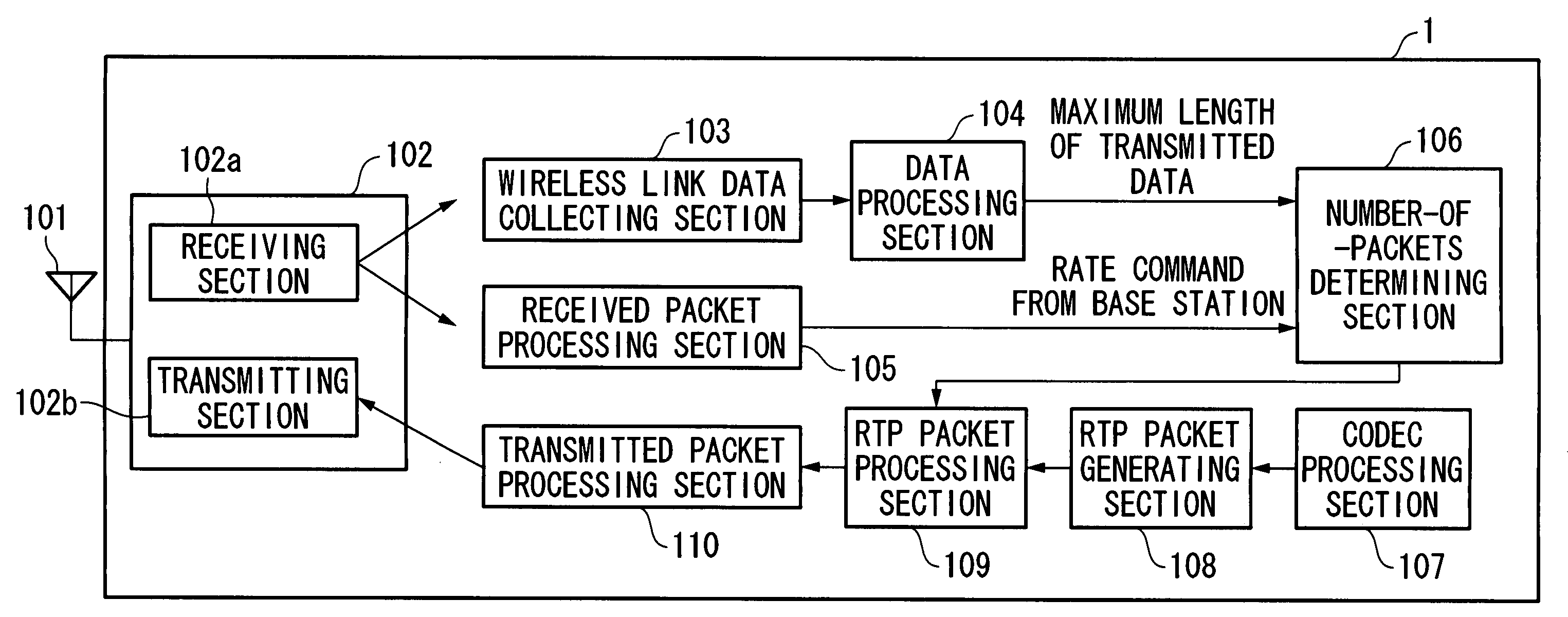
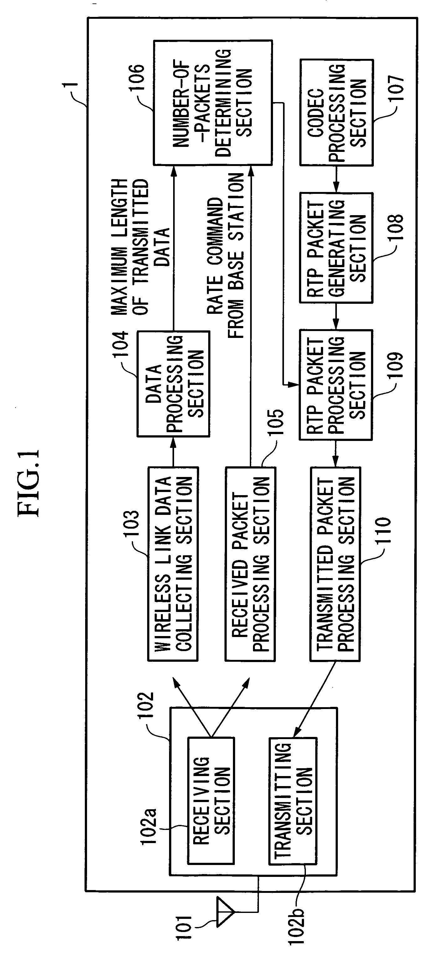
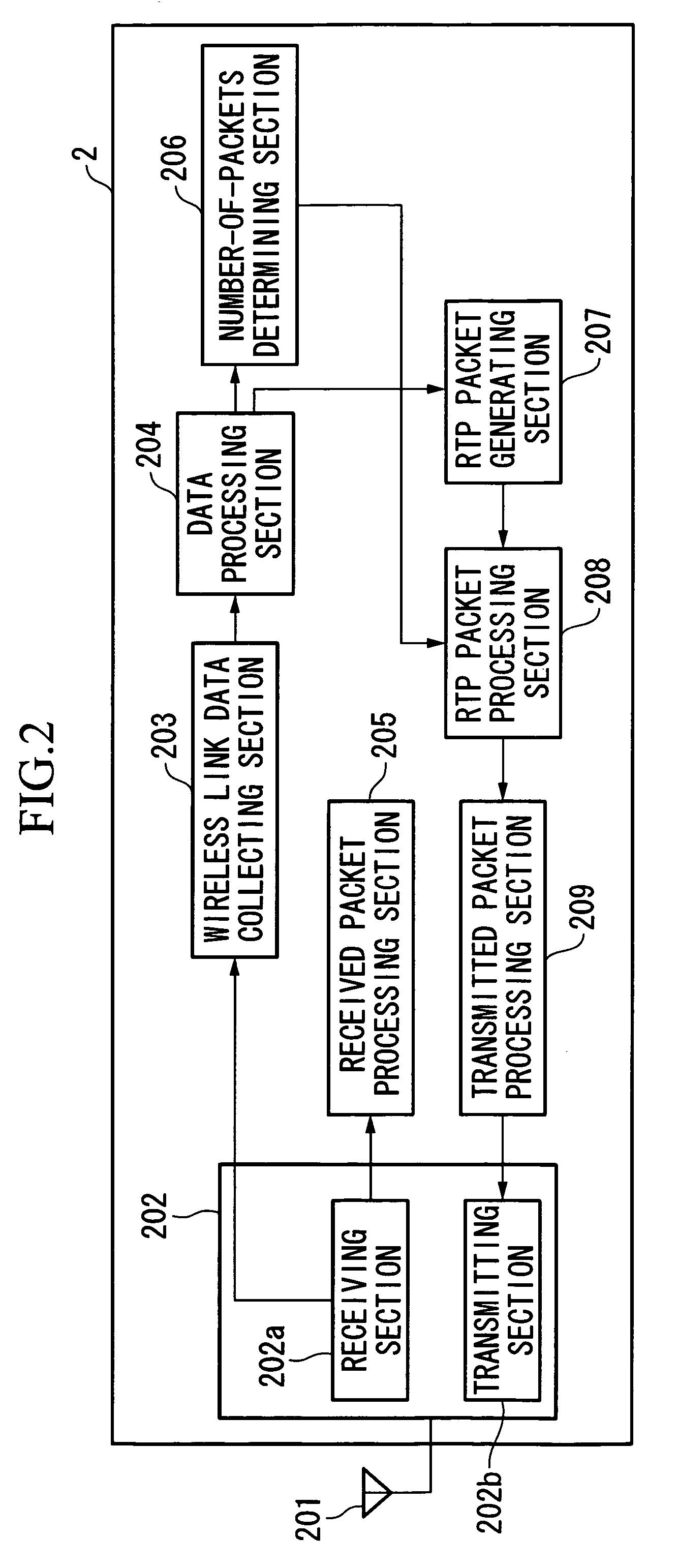
[0038]FIG. 3 is a diagram showing the structure of a wireless communication system in accordance with an embodiment of the present invention. In the wireless communication system of the present embodiment, adaptive modulation and demodulation are performed in up link and down link (i.e., up transmission and down transmission), and the data modulation method and the encoding ratio in channel encoding are adaptively controlled in accordance with the state of wireless links, so that the packet length (i.e., the number of bits) of a wireless frame is adaptively varied. Here, a CDMA2000 1xEV-DO system will be explained as an example of the wireless communication system. In the present embodiment, a user terminal 1 and a base station 2 as wireless communication apparatuses communicate with each other using RTP packets for VoIP (i.e., packets for real-time...


PUM


Abstract

A wireless communication method includes determining the number of packets for real-time communication, which are inserted in a wireless frame whose number of bits is adaptively varied; inserting the packets for real-time communication in the wireless frame, wherein the number of the packets are determined by the determining step; and transmitting the wireless frame. A wireless communication apparatus has a number-of-packets determining section for determining the number of packets for real-time communication, which are inserted in a wireless frame the number of bits of which is adaptively varied; an inserting section for inserting the packets for real-time communication in the wireless frame, wherein the number of the packets are determined by the number-of-packets determining section; and a transmitting section for transmitting the wireless frame. The number of the packets may be determined based on a transmission rate, an encoding ratio, or a modulation method for transmission of the wireless frame.

Description

BACKGROUND OF THE INVENTION [0001] 1. Field of the Invention [0002] The present invention relates to a wireless communication method and apparatus for improving efficiency of data communication through a wireless communication path. [0003] Priority is claimed on Japanese Patent Application No. 2005-152017, filed May 25, 2005, the content of which is incorporated herein by reference. [0004] 2. Description of the Related Art [0005] VoIP (voice over Internet protocol) is a known protocol for sending and receiving voice data on an IP (Internet protocol) network. A technique disclosed in Reference Document 1 (Japanese Unexamined Patent Application, First Publication No. 2004-128603) may be applied to a wireless communication system in which not only RTP (real-time transport protocol) packets for VoIP but also packets for data communication (e.g., TCP (transmission control protocol) packets) are simultaneously processed. In the disclosed technique, received packets are classified into QoS...

Claims


Application Information

Patent Timeline
Patent Type & Authority Applications(United States)
IPC IPC(8): H04L12/56H04W28/00H04W28/06H04W28/18
CPCH04L29/06027H04L69/324H04L69/32H04L65/608H04L65/65H04L69/327H04L69/325H04L69/326H04L65/00H04L65/1101
Inventor YOKOTA, TOMOYOSHI
Owner KYOCERA CORP
Why Eureka
Try Eureka