
Multi-configurable switch mode charging system, charging circuit, and charging method

Active Publication Date: 2018-01-25
SILICON MITUS
View PDF3 Cites 13 Cited by
  • Summary
  • Abstract
  • Description
  • Claims
  • Application Information

AI Technical Summary

Benefits of technology

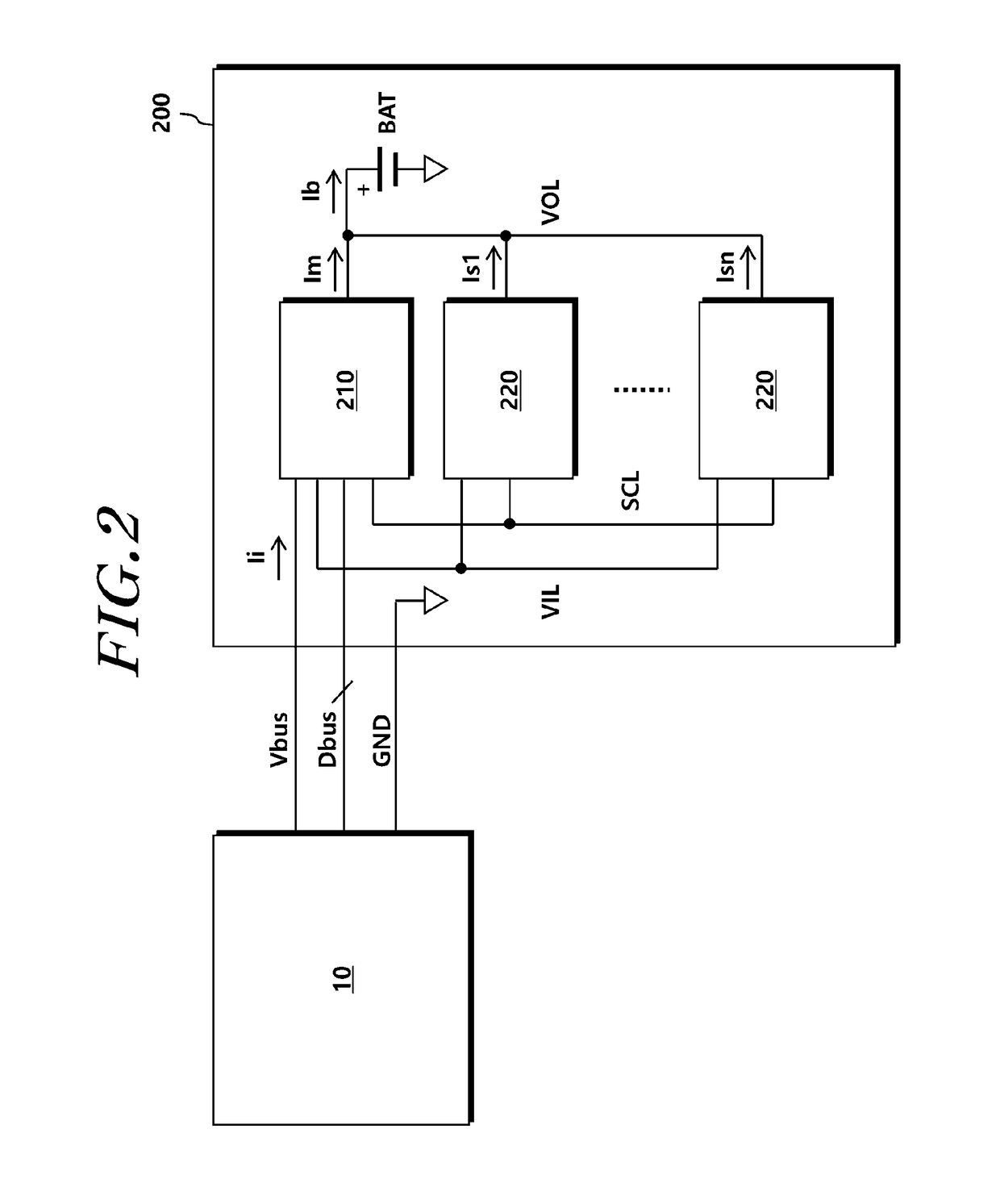
The present invention simplifies communication between charging circuits in a charging system with multiple circuits. It uses a single-wire interface, reducing complexity and making the circuit area smaller. The communication is performed through analog circuits alone, without needing any additional digital communication processing. Overall, the invention improves efficiency and reduces costs in charging systems.

Problems solved by technology

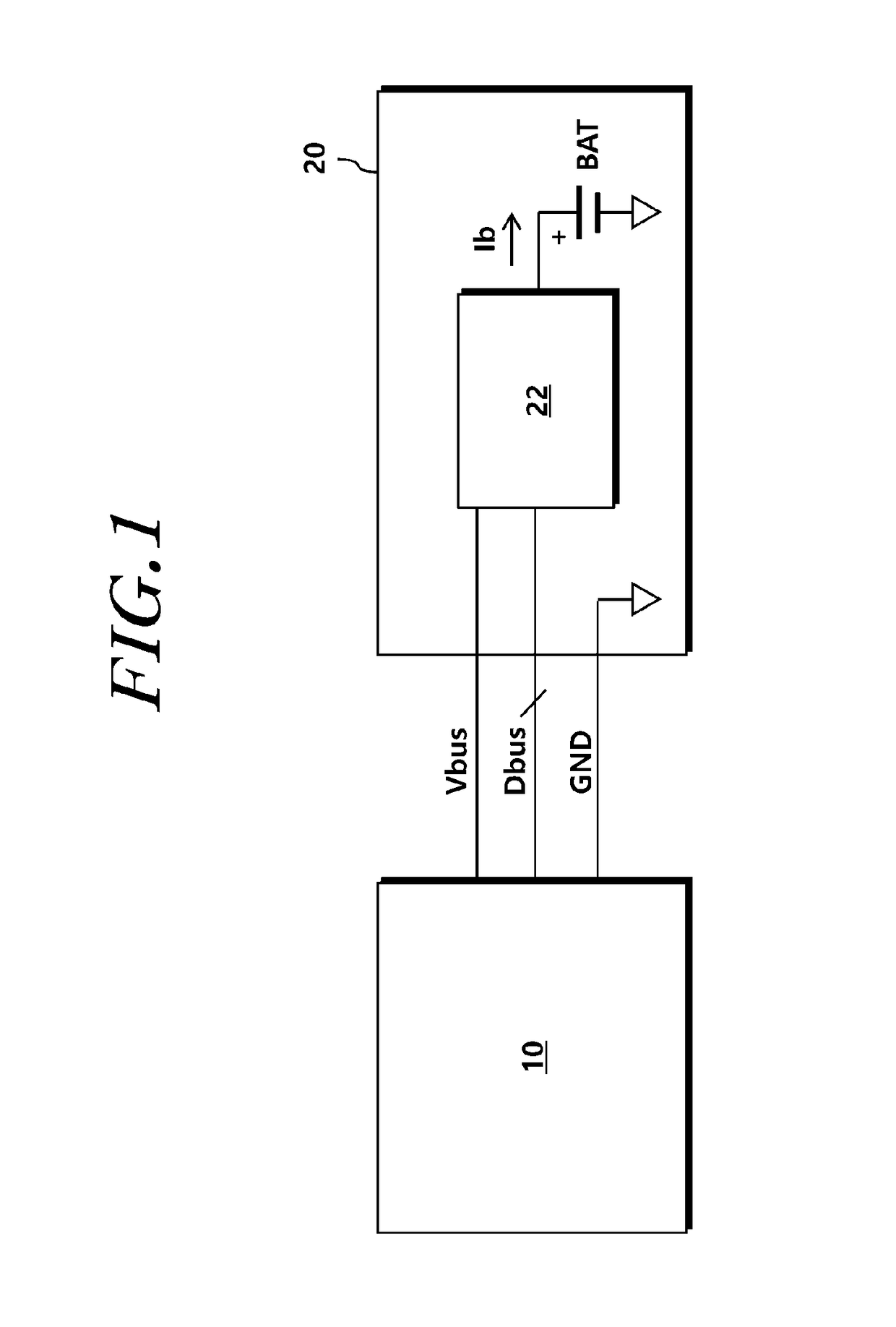
Accordingly, there is a limitation in the charging current Ib that one charging circuit (22) can supply to the battery BAT, and thus the USB charging system (20) has a limitation in the charging time of the battery BAT due to the limitation.

Method used


Image

  • Multi-configurable switch mode charging system, charging circuit, and charging method
  • Multi-configurable switch mode charging system, charging circuit, and charging method
  • Multi-configurable switch mode charging system, charging circuit, and charging method

Examples


Embodiment Construction

[0029]Hereinafter, embodiments of the present invention will be described in detail with reference to the accompanying drawings. In adding reference numerals to elements in each drawing, the same elements will be designated by the same reference numerals, if possible, although they are shown in different drawings. Further, in the following description of the present invention, a detailed description of known functions and configurations incorporated herein will be omitted when it is determined that the description may make the subject matter of the present invention rather unclear.

[0030]In addition, terms, such as first, second, A, B, (a), (b) or the like may be used herein when describing components of the present invention. These terms are merely used to distinguish one structural element from other structural elements, and a property, an order, a sequence and the like of a corresponding structural element are not limited by the term. It should be noted that if it is described in ...


PUM


Abstract

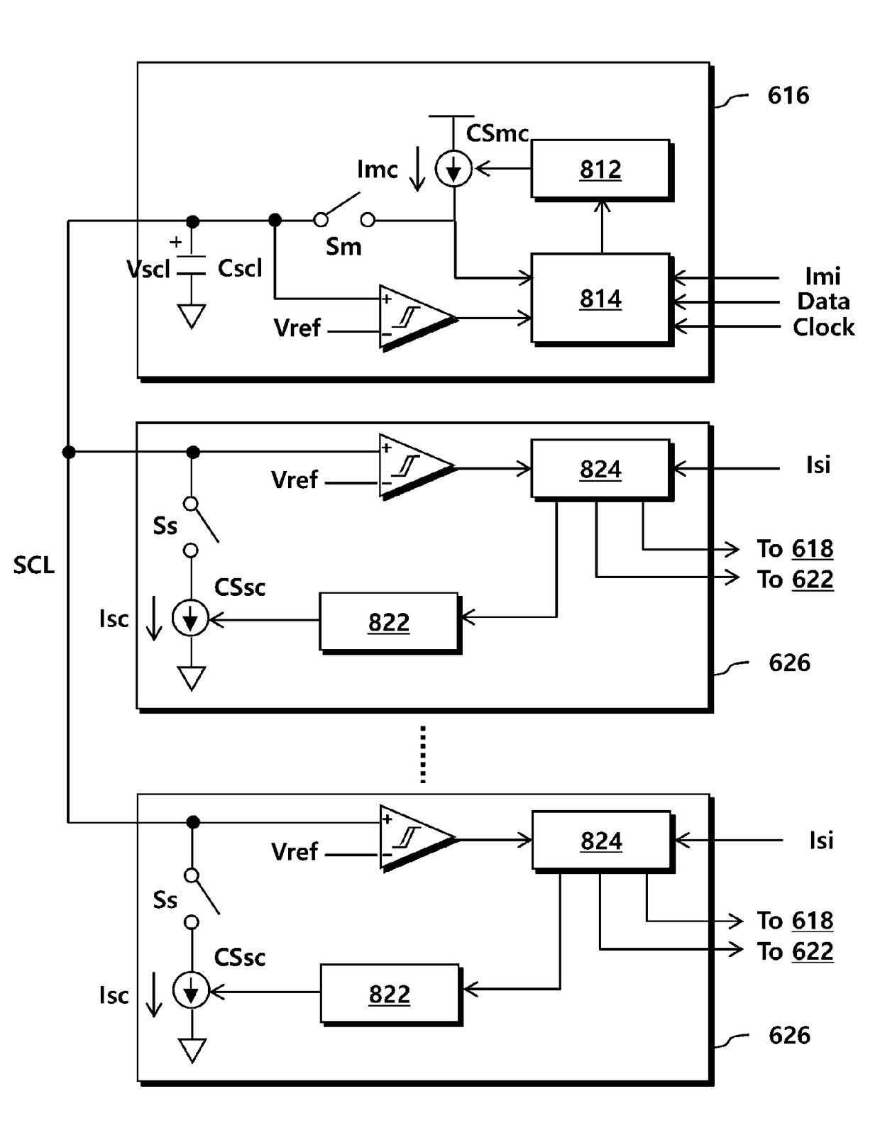
A method of charging a battery by a charging system comprising a master charging circuit and N (N is a natural number) slave charging circuits. The method includes: sourcing a first current to a single-wired bus by the master charging circuit; absorbing (sinking) a second current from the single-wired bus by the N slave charging circuits connected to the single-wired bus; identifying a single-wired bus voltage formed on the single-wired bus at a particular time point by the master charging circuit; and identifying the number of slave charging circuits based on the single-wired bus voltage by the master charging circuit.

Description

CROSS REFERENCE TO RELATED APPLICATION[0001]This application claims priority from Korean Patent Application No. 10-2016-0091227, filed on Jul. 19, 2016, which is hereby incorporated by reference for all purposes as if fully set forth herein.BACKGROUND OF THE INVENTION1. Field of the Invention[0002]The present invention relates to a charging technology. More particularly, the present invention relates to a multi-configurable switch mode charging technology.2. Description of the Prior Art[0003]FIG. 1 is a block diagram illustrating a generally used Universal Serial Bus (USB) charging system.[0004]A USB charging system (20) receives power from a USB host (10) and charges a battery BAT within the USB charging system (20).[0005]The USB charging system (20) is connected to the USB host (10) through four cables, wherein one of the four cables corresponds to a power bus Vbus that receives charging power and another cable corresponds to a ground line GND for adjusting a ground level. Further...

Claims


Application Information

Patent Timeline
IPC IPC(8): H02J7/00
CPCH02J7/0068H02J2007/0096H02J7/0081H02J7/0029H02J2207/20H02J2207/30H02J7/00034H02J7/00H02J7/007184Y02B40/00
Inventor SHIN, HO JUNLEE, KANG YOONCHOI, KWANG MUKJANG, IL KWONSEO, HAN SUKPARK, HYUNG GUPARK, YOUNG JUNOH, SEONG JINPARK, JU HYUNKIM, JUNG YEON
Owner SILICON MITUS
Learn More