Laser Indicator System

a laser indicator and indicator technology, applied in the direction of metal-working machine components, instruments, manufacturing tools, etc., can solve the problems of loss of revenue, inability to maintain the group within the present tolerance limit, and laborious methods

Inactive Publication Date: 2012-08-09
LINDEE SCOTT A
View PDF1 Cites 14 Cited by
  • Summary
  • Abstract
  • Description
  • Claims
  • Application Information

AI Technical Summary

Problems solved by technology

Food product drafts are sold according to a precise predetermined weight; under-weight drafts are rejected or supplemented with additional food slices and over-weight drafts are accepted but may represent an appreciable give-away and loss of revenue to the plant operator.
Even with advanced controls, the slicing machines and like food product machines that produce groups of food products cannot always maintain those groups within the present tolerance limit.
The present inventor has recognized this method is labor intensive.

Method used


Image

  • Laser Indicator System
  • Laser Indicator System
  • Laser Indicator System

Examples


Embodiment Construction

[0026]While this invention is susceptible of embodiment in many different forms, there are shown in the drawings, and will be described herein in detail, specific embodiments thereof with the understanding that the present disclosure is to be considered as an exemplification of the principles of the invention and is not intended to limit the invention to the specific embodiments illustrated.

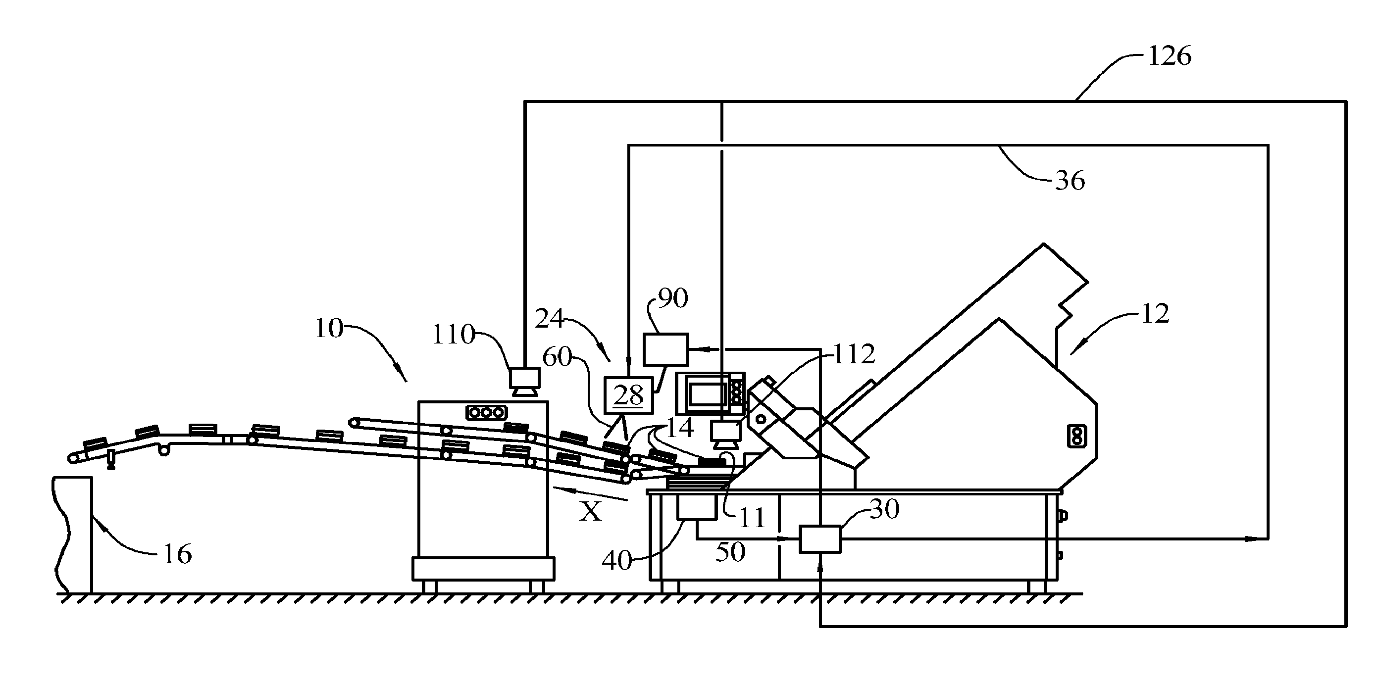
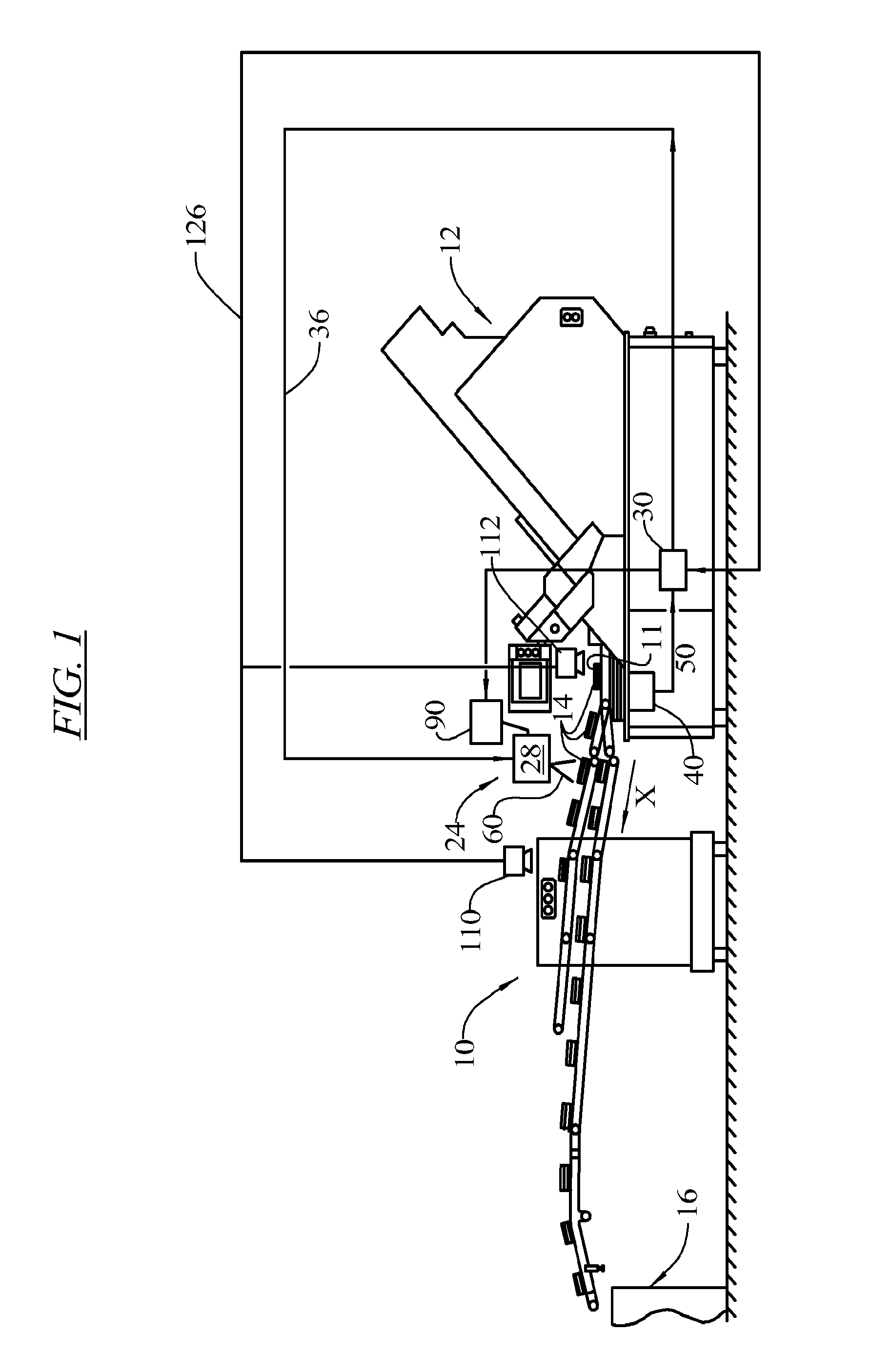
[0027]FIG. 1 is a side elevation view of a conveyor system 10 fed sliced products 11 by a food slicing machine 12, such as a FX180® or PowerMax 4000™ slicer from Formax, Inc. of Mokena, Ill., USA.

[0028]The slices 11 are collected on the conveyor system 10 as a stacked draft, shingled draft or loose draft 14 that are translated in the direction “X” on a conveyor surface 15 toward a packaging station 16.

[0029]A laser indicator system 24 contains at least one laser device 28 that communicates with a food slicing machine control unit 30 via a signal carrier, such as a cable 36.

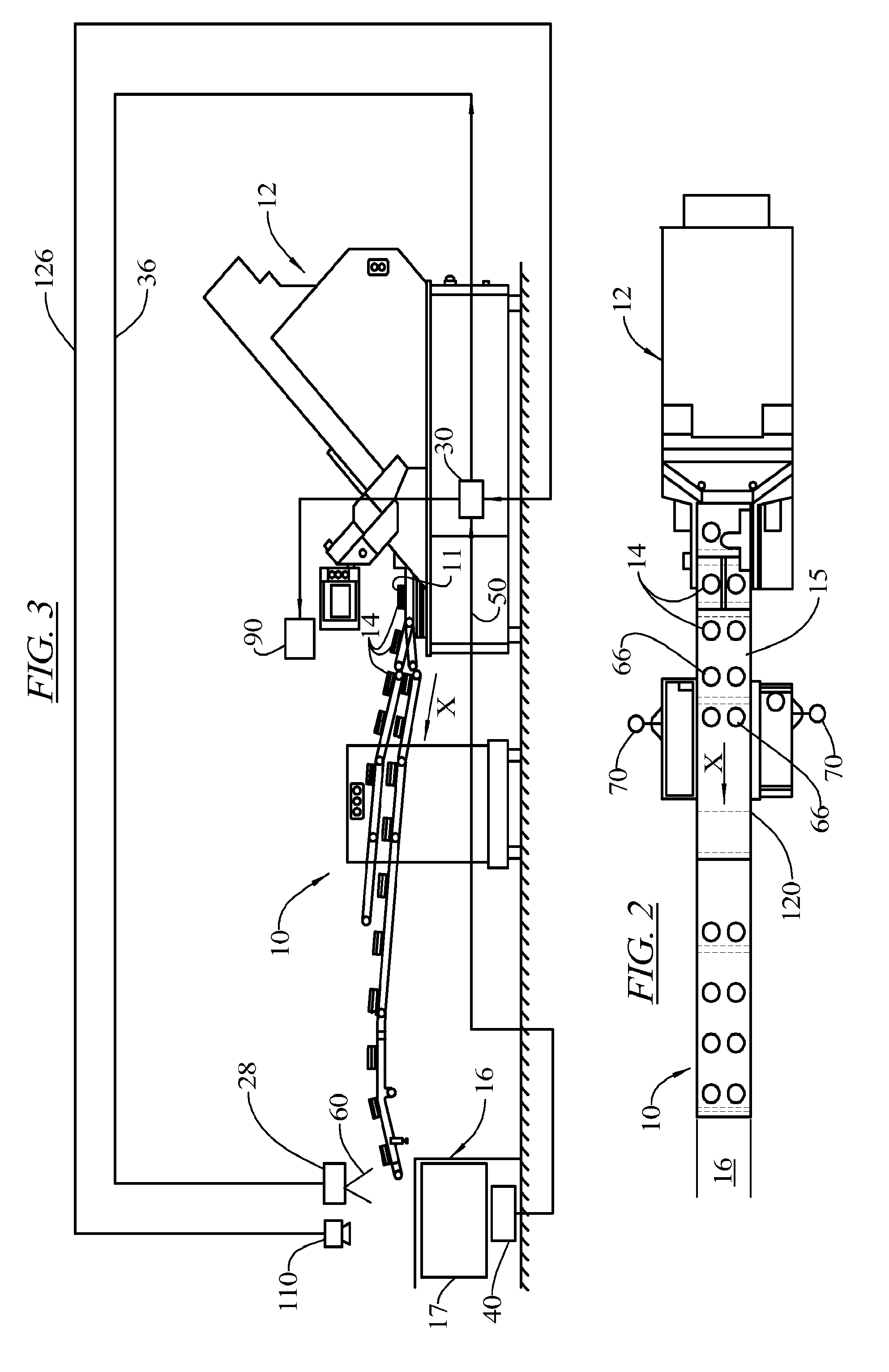
[0030]FIG. 2 is a plan ...


PUM

PropertyMeasurementUnit
weightaaaaaaaaaa
thicknessaaaaaaaaaa
off-weightaaaaaaaaaa

Abstract

A weight correction system for a slicing apparatus includes a weigh scale that weighs a draft of slices output from a slicer, a laser device arranged above the drafts of slices from the slicer, and a control that assigns a weight to each draft of slices, compares the weight to a pre-selected acceptable weight and determines a correction indicator representative of the number of slices to be added to or subtracted from each draft. The control commands the laser device to project the correction indicator onto a top slice of the draft. The laser device can project the correction indicator onto the draft as the draft is moving on a conveyor, or the laser device projects the correction indicator onto the drafts when the drafts are stationary, such as when the drafts are stationary in a packaging station.

Description

FIELD OF THE INVENTION[0001]The invention relates to a system used to monitor groups of food slices for correct weight.BACKGROUND OF THE INVENTION[0002]In food processing, food product drafts can be a single food portion or a group of food portions such as a stack of slices. Food product drafts are sold according to a precise predetermined weight; under-weight drafts are rejected or supplemented with additional food slices and over-weight drafts are accepted but may represent an appreciable give-away and loss of revenue to the plant operator.[0003]Even with advanced controls, the slicing machines and like food product machines that produce groups of food products cannot always maintain those groups within the present tolerance limit. To minimize waste, it is desirable to correct any out-of-tolerance or “reject” food product groups.[0004]U.S. Pat. No. 5,109,936 to Ruppel describes a system that includes a slicing machine having a slicing blade and a feed mechanism, and uses feedback ...

Claims


Application Information

Patent Timeline
Patent Type & Authority Applications(United States)
IPC IPC(8): B26D7/30G01G23/36B26D7/32
CPCB26D7/30B26D2210/02G01G23/32G01G13/2906G01G19/42G01G15/02Y10T83/0448Y10T83/145
Inventor LINDEE, SCOTT A.
Owner LINDEE SCOTT A
Why Eureka
Try Eureka